
CAN Interface Basics: Controller Area Network
By RF Wireless Expert Team
Advertisement
This page describes CAN interface basics and provides links to other useful interfaces such as RS232, RS485, RS422, SPI and DigRF.
CAN is the short form of Controller Area Network. Its design allows devices to communicate with each other without needing a single host PC. It’s primarily targeted for microcontroller-based applications and is widely used in automotive, medical, and networking applications.
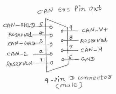
The CAN interface is used with a CAN bus, a differential 2-wire interface. Data communication over CAN uses NRZ encoding for bit encoding. It typically employs a 9-pin D-type male connector for all nodes to communicate on the CAN bus. The following figure and table outline the key aspects:
CAN Bus Pin Details
| Signal Name | Description | Pin |
|---|---|---|
| Reserved | Future use | 1 |
| CAN_L | CAN dominant low signal | 2 |
| CAN_GND | Ground | 3 |
| Reserved | Future use | 4 |
| CAN_SHLD | Shield (Optional) | 5 |
| GND | Ground (Optional) | 6 |
| CAN_H | CAN dominant high signal | 7 |
| Reserved | Future use | 8 |
| CAN_V+ | Power (Optional) | 9 |
Continue Learning CAN Protocol
- Standard Vs. Extended CAN Frame Format
- CAN Bus : Key Advantages & Disadvantages
- CAN-FD : Key Advantages & Disadvantages
- CANopen : Key Advantages & Disadvantages
- CAN Controller Vs. CAN Transceiver
- CAN Bus Error Types
- CAN Bus Frame Types
- What is Dominant and Recessive Bit in CAN Bus
- Function of TEC and REC in CAN Bus
- What is CAN Controller : Popular Manufacturers
- What is CAN Transceiver : Popular Manufacturers