
What is difference between EEIRP EIRP ERP in NTN Measurement
Advertisement
EEIRP, EIRP, and ERP are key radiated power measurements used in NTN (Non Terrestrial Network) systems. EEIRP represents equivalent effective isotropic radiated power, EIRP measures power relative to an isotropic antenna and ERP references a dipole antenna. Knowing their differences is critical for accurate satellite and wireless network performance evaluation.
EIRP (Effective Isotropic Radiated Power)
EIRP is the measured radiated power of a transmitter and its antenna in a single, specific direction, compared to a theoretical “isotropic” antenna. An isotropic antenna is an idealized point source that radiates power perfectly uniformly in all directions (a sphere).
When a 5G or 6G system uses beamforming, it concentrates the transmitter’s power into a narrow beam. EIRP tells you how much power a theoretical isotropic antenna would need to radiate to achieve the exact same signal strength in that specific target direction.
Following is the formula for EIRP calculation.
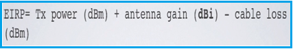
EIRP is the standard metric for Over The Air (OTA) output power testing. In NTN and mmWave (FR2) communications, EIRP is heavily used to calculate link budgets to satellites or distant receivers. It focuses on the peak direction of the beam.
Example (EIRP Calculation):
- TxP (Transmit Power) = +20 dBm
- L (Cable Loss) = -5 dB
- Gt (Antenna Gain) = +10 dBi
=> EIRP in dBm = +20 - 5 + 10 = 25 dBm
ERP (Effective Radiated Power)
ERP is almost identical in concept to EIRP, but instead of using a theoretical isotropic antenna as the baseline, it uses a standard half wave dipole antenna.
A half wave dipole is a real world antenna that does not radiate equally in all directions; it naturally concentrates power in a donut shape, giving it an inherent gain of 2.15 dB over an isotropic radiator.
Following is the formula for ERP calculation.
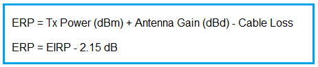
While high-frequency 5G (mmWave) and NTN systems overwhelmingly use EIRP, regulatory bodies (like the FCC or ITU) often specify limits in ERP for sub-6 GHz terrestrial bands due to historical legacy. It is primarily used for regulatory compliance rather than advanced beamforming modeling.
Example (ERP Calculation):
Let’s say we have:
- TxP (Transmit Power) = +20 dBm
- L (Cable Loss) = -5 dB
- Gt (Antenna Gain) = +7.85 dBd
=> ERP = 22.85
EEIRP (Expected Equivalent Isotropic Radiated Power)
EEIRP is a newer, highly specialized metric used heavily in advanced 3GPP conformance testing (such as for Network Controlled Repeaters). Unlike EIRP, which measures power in one specific point/direction, EEIRP represents the spatially averaged power over a specific geometric region.
How EEIRP is measured
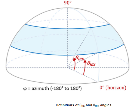
Advanced 5G and 6G arrays generate multiple dynamically steered beams. EEIRP calculates the expected interference or emission levels not just at the beam’s peak, but averaged over a “spherical strip” or angular sector. It requires a two-step averaging process:
- Averaging the EIRP over various active test beam directions.
- Averaging those results over a grid of horizontal (azimuth) and vertical (elevation) angles.
Following is the formula for EEIRP calculation.
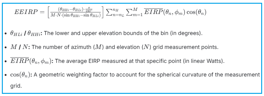
EEIRP is crucial for spatial emission testing. For example, when terrestrial 5G/6G systems operate near frequencies used by the Fixed Satellite Service (FSS), EEIRP is used to ensure that the aggregate, time averaged beamforming energy leaking into the sky does not blind orbiting satellites. It provides a realistic model of interference from dynamic beamsteering, rather than a worst case static peak.
Difference between ERP EIRP EEIRP
| Feature | EIRP | ERP | EEIRP |
|---|---|---|---|
| Reference Antenna | Isotropic (perfect sphere, 0 dBi) | Half Wave dipole (2.15 dBi) | Isotropic (Perfect Sphere, 0 dBi) |
| Spatial Nature | Point specific, Measures peak power in one exact direction. | Point specific, Measures peak power in one exact direction. | Region specific, Measures spatially averaged power over a defined angular grid or sector. |
| Primary Focus | Maximum signal strength for link budgets and beam peaks. | Regulatory limits, usually in lower frequency bands. | Spatial emissions, co-existence, and modeling aggregate interference. |
| Relation to Beamforming | Evaluates the “loudness” of a single beam. | Evaluates the “loudness” of a single beam (using a dipole reference). | Evaluates the “average noise footprint” of dynamic beams sweeping across an area. |
Summary : These antenna radiation metrics i.e. ERP, EIRP and EEIRP are essential for evaluating non terrestrial network (NTN) performance, satellite communications and wireless coverage. Understanding EEIRP vs EIRP vs ERP helps engineers compare transmit power, antenna gain and effective radiated signal strength accurately.
Tags
Advertisement


