Waveguide Bend Chamfer Formula & Calculator
Advertisement
In microwave waveguides (rectangular typically), mitering (a chamfer or cut on the bend corner) is used to reduce reflections and mismatch at a 90° bend by approximating a gradual turn with a folded metal mirror surface. This effectively compensates for the discontinuity that would otherwise occur at a sharp corner.
EXAMPLE:
INPUTS:
- Broad wall dimension = 22.86 mm (For WR-90 Waveguide type)
- Operating Frequency = 10 GHz
OUTPUTS:
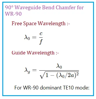
- Free space wavelength (λo)= 30 mm
- Guide Wavelength (λg) = 39.75 mm
- Quarter Guide Wavelength Path Length (Lmiter) = 9.93 mm
Waveguide Bend Chamfer for WR-90 Formula
Summary: Relative chamfering/mitering in microwave waveguide bends is used to minimize reflections and maintain impedance by matching the electrical path length through the corner to an approximate quarter of the guide wavelength at the center frequency.
References for further study
- https://www.microwaves101.com/
- Generic microwave engineering waveguide bend discussions