
Wi-Fi 7 network planning:Survey,link budget,deployment
Advertisement
Introduction : Wi-Fi 7 is one in the series of WLAN standards being developed under IEEE 802.11 family. The 802.11 standard defines PHY and MAC layer specifications. The Wi-Fi versions have evolved from 802.11a, 11b, 11g, 11n (WiFi 4), 11ac (WiFi 5), 11ax (WiFi 6), 11be (WiFi 7) and 802.11bn (Wi-Fi 8). These standards support different data rates and cell coverage.
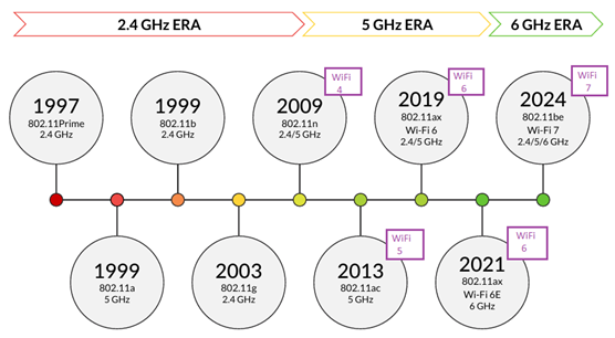
Figure:1 WiFi Standard Evolution
1. Wi-Fi 7 Features
The Wi-Fi 7 is based on IEEE 802.11be also known as EHT (Extremely High Throughput). It supports following features in comparison to its predecessors.
- Supports tri band of operation i.e. 2.4 GHz, 5 GHz and 6 GHz.
- Supports maximum channel bandwidth of 320 MHz.
- Supports maximum modulation type of 4096QAM.
- Supports maximum number of spatial streams (SSs) of 16.
- Supports Multi-Link Operation (MLO)
- Supports Preamble puncturing
The WiFi 7 offers ultra high throughput, lower latency and high reliability for various applications.
2. Wi-Fi 7 Channels in Tri Bands (2.4/5/6 GHz)
2.4 GHz is used for long range and low BW legacy devices. 5 GHz is used as balance between high speed and moderate range for video calls and streaming applications. 6 GHz is used for high priority dense traffic requiring ultra high speed and low latency. Following table mentions number of channels in 2.4 GHz, 5 GHz and 6 GHz as per FCC/ETSI.
Table-1 : 2.4 GHz WiFi Channels
| Channel Identifier | Center Frequency (MHz) |
|---|---|
| channel-1 | 2412 |
| channel-2 | 2417 |
| channel-3 | 2422 |
| channel-4 | 2427 |
| channel-5 | 2432 |
| channel-6 | 2437 |
| channel-7 | 2442 |
| channel-8 | 2447 |
| channel-9 | 2452 |
| channel-10 | 2457 |
| channel-11 | 2462 |
| channel-12 | 2467 |
| channel-13 | 2472 |
| channel-14 | 2484 |
Table-2 : 5 GHz WiFi Channels
| 5 GHz Channel Bandwidth | No. of FCC Channels | No. of ETSI Channels |
|---|---|---|
| 20 MHz | 24 | 23 |
| 40 | 11 | 10 |
| 80 | 7 | 6 |
| 160 | 3 | 2 |
Table-3 : 6 GHz WiFi Channels
| 6 GHz Channel Bandwidth | No. of FCC Channels | No. of ETSI Channels |
|---|---|---|
| 20 MHz | 59 | 24 |
| 40 MHz | 29 | 12 |
| 80 MHz | 14 | 6 |
| 160 MHz | 7 | 3 |
| 320 MHz | 3 | 1 |
- Channels 1, 6, 11 are the non-overlapping channels most widely used in the US.
- In Europe, channels 1, 5, 9, 13 can be used as non-overlapping (ETSI rules).
- Channel 14 (2484 MHz) is restricted to Japan and only supports legacy 802.11b.
- Wi-Fi 7 still supports the 2.4 GHz band, but with limited performance compared to 5 GHz/6 GHz.
What is BSA?
A Basic Service Area (BSA) is the geographical area covered by a single Access Point (AP) where client devices can maintain wireless connectivity. It represents the coverage footprint of an AP’s radio signal in a given band (2.4 GHz, 5 GHz, or 6 GHz). All devices within a BSA that connect to the same SSID (Service Set Identifier) and AP form part of a Basic Service Set (BSS). 2.4 GHz will have large BSA, 5 GHz will have medium and 6 GHz supports small BSA.
3. Pre-deployment : Site survey and Link Budget
A Wi-Fi heatmap is a graphical representation of wireless signal strength and performance across a physical area (office, campus, factory, home). It uses color gradients (green, yellow, red, blue) to show coverage, interference, and capacity zones. Heatmaps allow Wi-Fi 7 planners to design WiFi networks by optimizing AP placement, ensuring strong coverage, enabling high modulation schemes and minimizing interference.
At the start of the wifi network planning specifications of the client devices are usually not known or unavailable. Some organizations have strict specifications of allowed devices. WiFi Cell design requires different parameters such as AP power, channel bandwidth, allowed MCSs and desired data rates or throughputs. Table-4 mentions data rates of different class of devices as per bandwidth and number of special streams.
Table-4 : Different WiFi Client Devices
| Channel Bandwidth | IoT device (1SS) | Mobile (2SS) | Indoor AP (4SS) |
|---|---|---|---|
| 20 MHz | 172 Mbps | 344 Mbps | 688 Mbps |
| 40 MHz | 344 Mbps | 688 Mbps | 1376 Mbps |
| 80 MHz | 721 Mbps | 1442 Mbps | 2884 Mbps |
| 160 MHz | 1441 Mbps | 2882 Mbps | 5764 Mbps |
| 320 MHz | 2882 Mbps | 5764 Mbps | 11,528 Mbps |
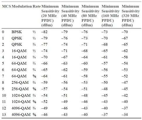
Table-5 : WiFi MCS Vs Receiver Sensitivity
3.1 Site Survey for AP Placement
Once specifications of client devices and coverage requirement for different floors are known, appropriate AP is choosen as per WiFi standard versions and MCSs are set in them. Table 5 mentions cell area coverage for different wifi versions as per highest modulation types along with SNR required.
Table-6 : WiFi Cell Coverage Vs Modulation
| WiFi Standard | Maximum Modulation | Approx. Cell Area | Required SNR (dB) |
|---|---|---|---|
| 802.11n | 64 QAM | ~ 2800 m^2 | ~ 24 dB |
| 802.11ac | 256 QAM | ~ 1800 m^2 | ~ 30 dB |
| 802.11ax | 1024 QAM | ~ 900 m^2 | ~ 36 dB |
| 802.11be | 4096 QAM | ~ 300 m^2 | ~ 42 dB |
Note : SNR values mentioned in the table above are ballpark figures for reliable demodulation in lab conditions. Real world scenarios may require higher SNR compared to the one mentioned in the table. This higher SNR are requirements due to external interference, multipath and fading.
The heatmap generation and analysis tools such as one from Ekahau helps to identify the best physical locations for Wi-Fi 7 APs to maximize coverage with minimal overlap. As heatmaps Shows where Wi-Fi 7 signals are strong (good RSSI/SNR) vs. weak (dead zones), planners can avoid under coverage (dead spots) and over coverage (waste of resources) regions.
3.2 RF Budget for WiFi Link
Following is the equation for link budget calculation. It is widely used in wireless systems including Wi-Fi 7 to estimate the received signal power at the receiver, given transmitter parameters, antenna characteristics and propagation losses.
P_RX = P_TX + G_TX – L_TX – L_FS – L_M + G_RX – L_RX
In the equation,
P_RX = The received signal level at the receiver.
P_TX = The output power of Wi-Fi 7 AP.
G_TX = The directional gain provided by transmitting antenna
L_TX = Transmit losses (in dB), due to cable, connector and filter losses.
L_FS = Free Space Path Loss (in dB), L_Fs = 32.44 + 20 log (d) + 20 log (f)
L_M = Fade Margin
G_RX = Gain of the receiving antenna
L_RX = Receiver Losses due to cable losses and impedance mismatches
P_RX > Receiver sensitivity threshold of MCS
Example calculation :
- Data Inputs : PTx = 20 dBm, GTx = 5 dBi , LTx = 1 dB, GRx = 2 dBi, LRx = 1 dB, Distance = 10 m, Frequency = 6 GHz
- Using equation and putting above values we will get PRx = -53 dBm, this is well above WiFi 7 specifications which is -65 to -75 as per MCS,
4. Wi-Fi Deplyment Guide
-
After performing site survey and determining power levels as per RF frequency requirements and link budget calculation tools, we can choose appropriate Access Point (AP) or router.
-
Choose AP which can handle required number of client devices along with their desired data rates.
-
Based on area to be served and analyzing heatmap collected, we can finalize on number of Access points and their specific location on various floors (if any).
4.1 AP Selection and Installation
- Access Point (AP) should be compliant to IEEE 802.11be (Wi-Fi 7) specifications with the features listed above. It should also be backward compatible with Wi-Fi 6/6E standards.
- Following are some of the popular vendors or manufacturers of Wi-Fi 7 AP or Router. Pls. check the latest datasheets to decide the right one as per your Wi-Fi network requirement.
- Cisco (Catalyst 9100 Series – Wi-Fi 7 roadmap)
- Aruba (HPE – Aruba 600 Series)
- Ruckus (CommScope – R770 Series)
- Ubiquiti UniFi (U7 Pro / U7 Enterprise)
- TP-Link Omada (EAP770 / EAP780)
- Netgear Orbi / Nighthawk Wi-Fi 7
4.2 Wi-Fi Infrastructure
There are three main types of infrastructure modes supported in Wi-Fi technology as explained below.
- Infrastructure Mode : This is most common mode. In this mode, client devices connect to an AP.The AP connects to wired network.
- Mesh Wi-Fi Infrastructure : In this mode, APs connect wirelessly to each other using wireless backhaul. For this AP to AP connectivity, WiFi 7 uses single 6 GHz band or it can use all three bands simultaneously as in MLO (Multi-Link Operation).
- Hybrid Infrastructure : This mode uses combination of wired and wireless backhaul (e.g., Cat6a + MLO).
5. Wi-Fi Tools
- Following table mentions consolidated list of tools and their role and use cases in Wi-Fi 7 (802.11be) planning, deployment and troubleshooting.
Table-7 : Wi-Fi Signal troubleshooting and monitoring tools
| Tool manufacturers | Products/Features |
|---|---|
| Wireshark | Captures Wi-Fi frames (802.11 a/b/g/n/ac/ax/be). Analyzes management/control/data frames. |
| Keysight Technologies | IxChariot Software (Traffic simulation & performance testing) |
| Ekahau Inc. | Ekahau AI Pro & Ekahau Sidekick 2 : Professional Wi-Fi design & site survey tool |
| NetAlly, LLC | AirMagnet Survey Pro & WiFi Analyzer : Used for real time RF Spectrum Analysis |
| 7SIGNAL, Inc. | Offers cloud based WiFi performance monitoring platform |
- Following table mentions Test and Measurement Equipments used by chipset vendors, AP manufacturers and test labs to generate, analyze and validate Wi-Fi Signals including Wi-Fi 7, Wi-Fi 6/6E etc.
Table-8 : Wi-Fi Signal Generation and Analysis T&M Equipments
| T&M Company | Products/Features |
|---|---|
| Rohde & Schwarz | Offers Vector Signal Generator, Vector Signal Explorer and Spectrum Analyzer etc. Check-out R&S website for latest products and their features. |
| Keysight Technologies | Offers WiFi waveform generation and modulation analysis tools. |
| Anritsu Corporation | MT8862A : WLAN test solution, MG3710E : Wi-Fi 7 Waveform generator, MS2090A : Portable wifi interference and spectrum troubleshooting equipment |
| LitePoint, a Teradyne company | IQxel-MW 7G : Wi-Fi 7 Test system, IQgig-5G: RF parametric test system for WiFi chipsets, IQxel-MX : WLAN tester for Wi-Fi 6/6E and can be evolved to Wi-Fi 7. |
| Other Vendors | Check-out Spirent, National Instruments and Viavi solutions. |
Conclusion: Wi-Fi 7 radio network planning is no longer just about “coverage”. It is about delivering guaranteed user experience by combining smart frequency selection, optimized AP placement, efficient channel reuse, reliable backhaul and continuous monitoring with professional tools. With careful planning, Wi-Fi 7 can unlock the full potential of next generation applications such as immersive AR/VR to smart factories and ultra dense enterprise environments.
Advertisement


