Waveguide Basics: Types, Propagation Modes, Advantages & Disadvantages
Advertisement
Introduction
Electromagnetic waves are transported from one location to another using various methods, including coaxial cables, two-wire lines, optical fibers, microstrip lines, and waveguides.
Waveguides are specialized, hollow metallic structures designed to guide electromagnetic waves efficiently. They are widely used in microwave and RF communications, optical systems, and radar because they transmit signals with minimal loss.
Waveguides typically operate in the frequency range of 300 MHz to 300 GHz. Because they pass all frequencies above a specific cutoff frequency, they are considered high-pass filters.
This article explores waveguide types, propagation modes, matching devices, advantages, disadvantages, and dimensions.
Types of Waveguides
Waveguides are classified based on their shape, structure, and application. Here are the primary types:
-
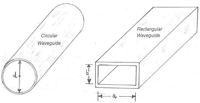
Rectangular Waveguides: Commonly used in microwave applications.
- Structure: A rectangular, hollow metallic tube.
- Advantages: Handles high power and is relatively easy to manufacture.
-
Circular Waveguides: Cylindrical in shape, mainly used for Transverse Electric (TE) and Transverse Magnetic (TM) modes. Suitable for applications requiring circular symmetry.
-
Elliptical Waveguides: Feature an elliptical cross-section. Used in optical fiber communication due to their lower polarization dependency.

-
Dielectric Waveguides: Made of dielectric material instead of metal. Typically used in optical communication and integrated circuits.
-
Flexible Waveguides: Constructed from flexible metallic materials. Used where bending or movement is required, like in radar systems.
-
Ridge Waveguides: A variant of the rectangular waveguide featuring a ridge. Offers better bandwidth and lower cutoff frequencies.
Cutoff Frequency of Rectangular & Circular Waveguides
The cutoff frequency is a critical parameter for waveguides. The formulas are as follows:
Rectangular Waveguide Cutoff Frequency
Where:
a= width of the waveguideb= height of the waveguide (typically half the width for standard waveguides, providing the optimal aspect ratio)m= number of half-waves along the broad side dimensionn= number of half-waves along the shorter sidec= speed of light
For the dominant mode TE10:
- m = 1, n = 0
- (where is the cutoff wavelength)
Circular Waveguide Cutoff Frequency
Where:
cis the speed of light within the waveguide.ais the radius of the circular cross-section.
For the dominant mode TE11:
- (where
dis the diameter)
The dimensions also dictate the operating frequency range. For practical use, the operating frequency should be at least 1.25 times the cutoff frequency to avoid mode interference.
Waveguide Propagation Modes
-
Waveguides support various TE and TM modes. The mode with the lowest cutoff frequency is called the dominant mode.
-
TE (Transverse Electric) mode: The electric field (E-field) is perpendicular to the direction of propagation, while the magnetic field (H-field) is in the direction of propagation.
-
TM (Transverse Magnetic) mode: The magnetic field is perpendicular to the direction of propagation, while the electric field is in the direction of propagation.
-
The dominant mode is TE10 for rectangular waveguides and TE11 for circular waveguides.
-
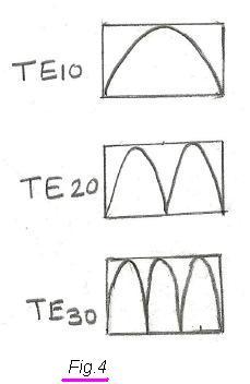
In TE10, the number ‘1’ indicates that one half-wave of the electric field exists along the X-direction. In TE20, the number ‘2’ indicates two half-waves exist along the X-direction.

Waveguide Impedance Matching Devices
These devices ensure efficient power transfer between waveguides and other components. Mismatched devices can lead to signal reflections and power loss. Common impedance matching devices include:
- Iris
- Posts or screws
- E-H tuner
- Probe
- Double stub tuner
These metallic elements are introduced into the waveguide near the source or where reflected waves are present to eliminate standing waves.

-
Iris: A thin metal plate with an aperture placed inside the waveguide. Used to introduce inductance (L), capacitance (C), or a combination of both into a rectangular waveguide. Different types include inductive, capacitive, and resonant irises, depending on how they’re inserted into the waveguide. Inductive irises are advantageous over capacitive ones in high-power applications. Resonant windows/irises produce combined inductive and capacitive effects.
-
Waveguide Tapers: Smoothly varying cross-sectional dimensions that provide gradual impedance matching between waveguides of different sizes.
-
Post/Screw: Acts as a shunt capacitive reactance in the waveguide if partially inserted. If fully inserted and connected to the waveguide wall on both sides, it introduces inductive reactance.
-
E-H Tuner: Used for waveguide tuning with hybrid tees. They allow continuous adjustment of both E and H arm reactance, removing any undesired reflections in a waveguide.
Waveguide-to-coaxial probes and double-stub tuners are also used for impedance matching.
Advantages of Waveguides
Waveguides offer several benefits in RF and microwave applications:
- Low attenuation for high-frequency signals.
- Ability to handle high power levels without breakdown.
- Metallic structure shields against external interference.
- Well-defined modes of propagation, minimizing signal distortion.
Disadvantages of Waveguides
Waveguides also have limitations:
- Larger and heavier compared to coaxial cables.
- Require high precision in design and construction.
- Rigid waveguides cannot be easily bent, limiting their use in flexible applications.
- Specific waveguide dimensions support specific frequency bands.
- Narrower bandwidth compared to other transmission lines.
- Power loss occurs in the waveguide walls due to induced current. The walls should be designed with the lowest possible resistance to mitigate this loss.
- Relatively high cost.
- The propagation of EM waves occurs due to reflection within the waveguide; hence, the TEM mode is not possible.
Waveguide Dimensions
The dimensions of a waveguide, particularly its width and height, are crucial as they determine the cutoff frequency for different modes.
For example, WR-62 indicates that the larger dimension is 0.62 inches, and the shorter dimension is half of that (0.31 inches).
Conclusion
Waveguides are essential components in high-frequency communication systems due to their low loss and high-power handling capabilities. By understanding the types, propagation modes, matching devices, and dimensions, engineers can design waveguide systems that meet the specific requirements of their applications. However, the bulkiness and manufacturing complexity must be carefully considered to determine if waveguides are the best option for a given scenario.
Advertisement
 RF
RF


