Dielectric Material Basics: Properties and Specifications
Advertisement
This page covers the basics and specifications of dielectric materials. We’ll look at materials like Duroid, PTFE-woven glass fiber, epoxy glass, and Alumina, which are commonly used as dielectric substrates. We’ll also explore the properties of various microwave substrates.
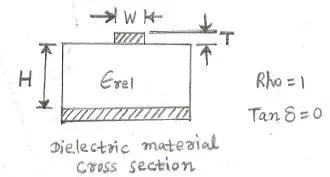
Figure: Cross section of a typical dielectric material.
Below are some popular dielectric materials that are very useful in RF and microwave high-frequency circuit design.
Dielectric Material Specifications
| Dielectric Material | Permittivity (ε) | T, Thickness of Pattern (50 Ohm Line) | W, Width of 50 Ohm Line |
|---|---|---|---|
| RT/Duroid | 2.3 | 0.015” | 0.044” |
| PTFE-woven Glass fiber | 2.55 | 0.010”, 0.031”, 0.062” | 0.25”, 0.079”, 0.158” |
| Epoxy-Glass | 4.8 | 0.062” | 0.108” |
| Alumina | 10.0 | 0.025”, 0.050” | 0.025”, 0.048” |
The dielectric materials listed above are chosen for RF and Microwave circuit design depending on the specific requirements of the application. Line width is a crucial factor when selecting the appropriate dielectric material for different RF/Microwave frequencies.
The dielectric material serves as the PCB for fabricating the RF circuit layout according to the design of various RF/microwave systems. Selecting the right dielectric substrate is vital for both size reduction and impedance matching.
To achieve a specific characteristic impedance, the transmission line needs to have the appropriate width (W). This width depends on the dielectric constant and the thickness of the dielectric substrate. Substrates with higher dielectric constants allow for smaller line widths on the substrate.
Low dielectric constant substrates are preferred for broadband, low-loss circuit designs.
Properties of Microwave Dielectric Substrates
| Dielectric Substrate | Dielectric constant | tan δ measured at 10GHz | Thermal Conductivity (W/cm-degreeC) |
|---|---|---|---|
| Si | 11.7-12 | 40-150 | 0.9 |
| GaAs | 12.8-13 | 16 | 0.3 |
| InP | 12.5-14 | NA | 0.68 |
| Alumina | 9.6-9.9 | 1-2 | 0.2 - 0.3 |
| Beryllia | 6.6-6.8 | 3 | 2.5 |
| Fused silica | 3.8 | <1 | 0.013 |
| Sapphire | 9.3-11.7 | <1 | 0.38-0.46 |
| Woven PTFF/glass, Non-woven | 2.2 | 9 | 0.0026 |
| PTFE/glass, Ceramic filled | 2.1 | 4.5 | Approx. 0.003 |
| PTFE/glass | 10.5 | 15 | 0.004 |
| Polyolefin | 2.3 | 1 | 0.001 |
| Ferrite/granite | 1316 | 2 | 0.03 |