 RF
RFPLL Frequency Pushing vs. Pulling: Understanding VCO Behavior
Advertisement
This article explains the basic differences between PLL (Phase-Locked Loop) frequency pushing and PLL frequency pulling. It also describes how to measure VCO (Voltage Controlled Oscillator) frequency pushing and pulling. These parameters are very useful in designing RF frequency synthesizers using a VCO, frequency divider, and loop filter.
A VCO takes a control voltage and a supply voltage as inputs and outputs a sine wave at a specific frequency. By keeping the control voltage and supply voltage constant, drift in the output frequency can be minimized.
Frequency pushing refers to a change in VCO frequency due to a change in the power supply voltage. A typical value for a mini-circuit VCO device is 0.30 MHz/V.
Frequency pulling refers to a change in VCO frequency due to a change in the load connected to the VCO output. A typical value for a mini-circuit VCO device is 0.80 MHz (peak-to-peak) at 12 dBr.
How to Measure VCO Frequency Pushing
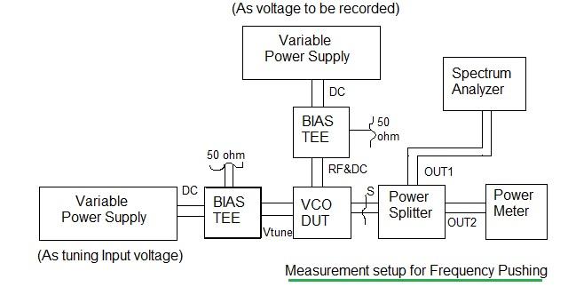
As mentioned earlier, VCO pushing is a result of the VCO’s sensitivity to the supply voltage. Figure 1 shows a measurement setup for VCO frequency pushing.
Here are the steps for the measurement:
- Initially, set the supply voltage to its normal value and note the VCO frequency.
- Vary the supply voltage and record the VCO frequency for these different voltages.
- Increment the supply voltage by 1 volt and record/measure the VCO frequency for different tuning values.
- Decrement the supply voltage by 1 volt and record the frequency for different voltages again.
- At one tuning voltage, the change in frequency caused by a 1-volt change will give you the frequency pushing figure of the VCO.
How to Measure VCO Frequency Pulling
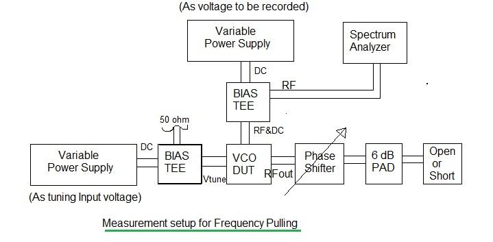
As mentioned, VCO pulling is a result of a non-ideal load connected to the VCO. Figure 2 shows a measurement setup for VCO frequency pulling. Because pulling is different and varies with frequency, it is measured at various points across the operational bandwidth.
Following are the steps for measuring VCO pulling:
- Set up the circuit as shown and use a bias tee to separate the RF and DC signals. The RF output is measured using a spectrum analyzer.
- Tune the phase shifter to get the maximum (or minimum) frequency with a short at the end of the RF output line.
- Obtain a reflected phase change of 180 degrees by replacing the short with an open.
- Fine-tune the phase shifter again to obtain the minimum (or maximum) frequency.
- Record the VCO frequency pulling using the peak search function on the spectrum analyzer.
Advertisement


