LTE PCFICH Channel: Physical Control Format Indicator Channel
Advertisement
This page describes the LTE PCFICH channel with respect to the LTE system.
The Physical Control Format Indicator Channel (PCFICH) is used at the start of each 1ms subframe. It provides information about the number of symbols used for PDCCH transmission.
The signaling values for PCFICH depend upon channel bandwidth. The same is mentioned in the following table:
| Channel Bandwidth | 1.4MHz | 3MHz | 5MHz | 10MHz | 15MHz | 20MHz |
|---|---|---|---|---|---|---|
| PCFICH values | 2,3,4 | 1,2,3 | 1,2,3 | 1,2,3 | 1,2,3 | 1,2,3 |
As mentioned, 1.4MHz requires more time domain symbols compared to other channel bandwidths due to fewer carriers in the frequency domain.
Signaling value depends on eNodeB RRM (Radio Resource Management). It depends on the number of active connections. Hence, PDCCH signaling increases as per the increase in the number of active connections.
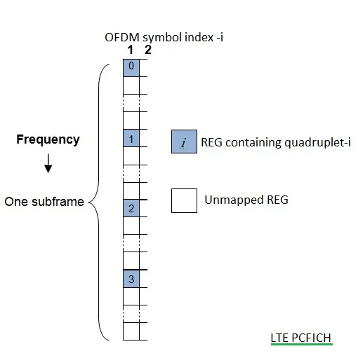
As shown in the figure, the LTE PCFICH channel occupies 16 REs (Resource Elements) in the first OFDMA symbol of each 1ms frame.
PCFICH uses QPSK modulation, and hence 16 REs will occupy 32 bits. These 16 REs are divided into 4 quadruplets. The position of which in the first OFDMA symbol depends on Channel BW and Physical layer cell identity. As mentioned, each quadruplet is mapped to a REG (Resource Element Group) with subcarrier index and is as per the following equation.
The rest of the three quadruplets are mapped to REGs spaced at intervals of from the first quadruplet and each other. This way, LTE PCFICH channel information is spread across the entire subframe as shown.
The PCFICH carries CFI (Control Format Indicator), which has a value ranging from 1 to 3. This CFI is coded to occupy the complete PCFICH capacity of 32 bits.
- Actual value = signaled value + 1 (for 1.4 MHz BW)
- Actual value = signaled value (for all the channel BWs)
Overhead due to LTE PCFICH channel
Like LTE PBCH, PCFICH also introduces overhead which reduces the number of resource elements needed for user plane data. As mentioned in the table below, the overhead is less for higher bandwidth and more for extended CP.
| 1.4MHz | 3MHz | 5MHz | 10MHz | 15MHz | 20MHz | |
|---|---|---|---|---|---|---|
| PCFICH REs per 1ms subframe | 16 | 16 | 16 | 16 | 16 | 16 |
| Normal CP Total REs per 1ms subframe | 1008 | 2520 | 4200 | 8400 | 12600 | 16800 |
| Overhead | 1.6% | 0.6% | 0.4% | 0.2% | 0.1% | 0.1% |
| Extended CP Total REs per 1ms subframe | 864 | 2160 | 3600 | 7200 | 10800 | 14400 |
| Overhead | 1.9% | 0.7% | 0.4% | 0.2% | 0.2% | 0.1% |
LTE PCFICH channel Reference: Document 3GPP TS 36.211