 RF
RFLTE NB-IoT NPDCCH: Function and Physical Layer Processing
Advertisement
This page describes the LTE NB-IoT NPDCCH function, its location, and its basics with respect to the LTE-NB IoT Standard. It covers LTE NB NPDCCH Physical Layer Processing and its applications within the system.
Function
The NPDCCH (Narrowband Physical Downlink Control Channel) is used to carry DCI (Downlink Control Information). The NB-IoT device extracts the following information from the NPDCCH channel:
- DCI format N0 with size 23 bits carrying UL grant information
- DCI format N1 with size 23 bits carrying DL scheduling information
- DCI format N2 with size 15 bits carrying SI update (or indicator of paging)
The following table lists useful information related to NPDCCH.
| NPDCCH information | Value |
|---|---|
| Subframe | Any |
| Basic TTI | 1 ms |
| Repetitions | 1, 2, 4, 8, 16, 32, 64, 128, 256, 512, 1024, 2048 |
| Subcarrier spacing | 15 KHz |
| Bandwidth | 90 KHz or 180 KHz |
| Carrier | Any |
Location
- The NPDCCH subframe is divided into two elements known as NCCEs (Narrowband Control Channel Elements). NCCE0 occupies the lower six subcarriers, whereas NCCE1 occupies the upper six subcarriers.
- After cell selection as well as SI acquisition process, the NB-IoT device comes to know the exact location/mapping of NPDCCH REs in the NPDCCH subframe.
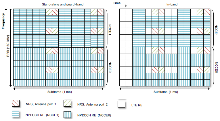
- In order to avoid the LTE DL control region in the in-band deployment mode, NPDCCH is not being mapped to the first few OFDM symbols in the subframe. Due to this, the index of starting OFDM symbols within the NPDCCH subframe depends on the LTE DL control region size.
The following table lists the possible number of REs per NCCE, which ranges from 50 to 80.
| Deployment mode | # LTE CRS antenna ports | # OFDM symbols for LTE control region | # NRS antenna ports | # REs per NCCE |
|---|---|---|---|---|
| Stand-alone, Guard band | NA | 0 | 1 | 80 |
| Stand-alone, Guard band | NA | 0 | 2 | 76 |
| In-band | 2 | 1 | 1 | 68 |
| In-band | 2 | 1 | 2 | 64 |
| In-band | 2 | 2 | 1 | 62 |
| In-band | 2 | 2 | 2 | 58 |
| In-band | 2 | 3 | 1 | 56 |
| In-band | 2 | 3 | 2 | 52 |
| In-band | 4 | 1 | 1 | 66 |
| In-band | 4 | 1 | 2 | 62 |
| In-band | 4 | 2 | 1 | 60 |
| In-band | 4 | 2 | 2 | 56 |
| In-band | 4 | 3 | 1 | 54 |
| In-band | 4 | 3 | 2 | 50 |
LTE NB NPDCCH Physical Layer Processing
A DCI can either be mapped to one NCCE known as AL-1 (Aggregation Level-1) or mapped to both NCCEs in the same subframe known as AL-2. AL-2 is useful in order to increase NPDCCH coverage.
- DCI is attached with a 16-bit CRC.
- CRC attached DCI is masked with RNTI (Radio Network Temporary Identifier).
- After CRC attachment and RNTI masking, TBCC encoding and rate-matching are applied to generate a codeword with a length equal to the available number of encoded bits.
- QPSK modulation is applied to NPDCCH as a result codeword length ranges from 100 to 160 for AL1 and from 200 to 320 for AL-2.
- The baseband waveform is generated using QPSK symbols as input.
Reference: 3GPP 36 series LTE
Advertisement


