 RF
RFDUC vs. DDC: Understanding Digital Up Conversion and Digital Down Conversion
Advertisement
This article explains the difference between Digital Up Conversion (DUC) and Digital Down Conversion (DDC). These modules are commonly used in Software Defined Radio (SDR) systems.
DUC: Digital Up Conversion
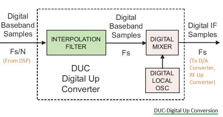
Figure 1 illustrates the block diagram of a DUC. As the name suggests, the function of a DUC is to convert digital baseband samples into digital Intermediate Frequency (IF) samples. The device that performs this conversion is known as a Digital Up Converter.
Following the DUC, a Digital-to-Analog Converter (DAC) is used to convert the digital IF samples into an analog IF signal. An RF up-converter then takes the analog IF signal and converts it to an RF signal for transmission. The IF translation frequency is determined by the Local Oscillator (LO).
Finally, an RF Power Amplifier amplifies the signal to compensate for path loss between the transmitting and receiving ends.
The Digital Up Converter consists of the following key modules:
- Interpolation Filter: This filter increases the sample frequency of the baseband signal.
- Digital Mixer: This mixes the interpolated signal with the signal from the Digital Local Oscillator.
- Digital Local Oscillator
Key Points about DUC Operation:
- The mixer generates one output sample for every two input samples.
- The sample frequency of the mixer output (and the input to the DAC) = Fs.
- The LO sample rate = Baseband Sample Rate = Fs
- Because the baseband sample frequency is much lower than the LO sample rate (Fs), an interpolation filter is crucial.
The interpolation filter increases the baseband signal’s sample frequency by a factor of N. This factor is known as the interpolation factor. The relationship between the required output sample rate and the input baseband sample rate is defined by the interpolation factor (N).
- Baseband bandwidth = 0.8 * Fb
- Output sample frequency Fs = Fb * N
DDC: Digital Down Conversion
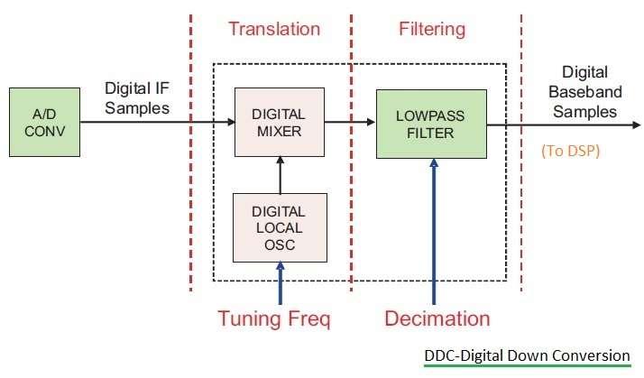
Figure 2 shows a block diagram of the DDC.
The role of the DDC is the opposite of the DUC: it converts digital IF samples into digital baseband samples. The device that performs this function is called a Digital Down Converter.
The Digital Down Converter consists of the following modules:
- Digital Mixer
- Digital Local Oscillator
- Low Pass Filter
In the decimation process, one sample is kept for every N digital samples. If the decimated output sample rate is more than twice the output bandwidth, no information is lost.
Decimated signals have a lower rate, which means they can be stored using less memory, reducing the overall system cost.
In summary, the DDC performs the following signal processing tasks:
- Frequency translation using a variable LO device.
- Low Pass filtering with bandwidth controlled by the decimation process.
The baseband signal bandwidth in the DDC is set using the decimation factor (N) and the lowpass FIR filter:
- Baseband sample frequency Fb = Fs / N
- Baseband bandwidth = 0.8 * Fb
Advertisement


