
Coplanar Waveguide: Advantages and Disadvantages
Advertisement
The coplanar waveguide (CPW) transmission line is a widely used planar transmission medium in RF and microwave circuits. It features a central conductive strip flanked by parallel ground planes on the same plane of a dielectric substrate. CPWs offer excellent electromagnetic confinement, broad bandwidth, and easy integration with active and passive components.
This guide explores the structure, functionality, and the advantages and disadvantages of CPW, making it an essential guide for understanding its role in high-frequency applications. In coplanar waveguide, EM energy is concentrated within the dielectric. The leakage of the Electromagnetic energy in the air can be controlled by having substrate height (h) twice that of the width (S).
The coplanar waveguide supports quasi TEM mode at low frequencies while it supports TE mode at high frequencies.
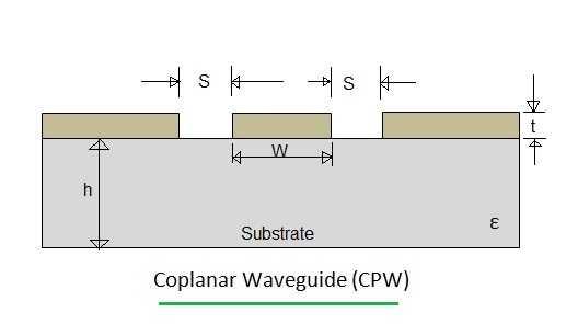
As shown in the figure, Coplanar Waveguide consists of a conductor strip at the middle, and two ground planes are located on either side of the center conductor. All these lie in the same plane. The effective dielectric constant of CPW is the same as that of a slotline.
The characteristic impedance of a coplanar waveguide is not affected by thickness and depends on width (W) and space (S). The lowest characteristic impedance of 20 Ohm can be achieved by maximum strip width (W) and minimum slot space (S). It typically ranges from 200 to 250 Ohm.
CPWs are particularly advantageous for integrating passive components like filters and antennas and are commonly used in high-frequency PCB designs, MMICs, and MEMS devices.
Advantages of Coplanar Waveguide
Following are some of the benefits of coplanar waveguide (CPW):
-
Ease of Fabrication: CPWs can be fabricated using standard planar PCB or MMIC processes, making them cost-effective and compatible with modern manufacturing techniques.
-
Reduced Radiation Losses: The coplanar design confines the fields within the dielectric, minimizing radiation losses.
-
Wideband Performance: CPWs offer excellent broadband characteristics due to the single-mode operation over a wide frequency range.
-
Compact Integration: They require less substrate height, enabling compact designs.
-
Easy Component Integration: The open structure facilitates the integration of active and passive components without the need for vias.
Disadvantages of Coplanar Waveguide (CPW)
Following are some of the drawbacks of Coplanar Waveguide:
-
Surface Wave Losses: CPWs may suffer from surface wave losses, especially on substrates with high dielectric constants.
-
Impedance Matching: Maintaining characteristic impedance requires precise design and control over substrate properties and dimensions.
-
Higher Conductor Losses: Compared to microstrip lines, CPWs exhibit slightly higher conductor losses due to current concentration on the edges.
-
Complex Modeling: CPWs require advanced simulation and modeling techniques for accurate characterization, particularly at high frequencies.
-
Substrate Dependency: The performance is highly sensitive to the substrate material, which may limit its usage in certain applications.
-
Expensive: Fabrication of coplanar waveguides is costlier, as gold ribbons are needed to suppress higher-order modes at every quarter wavelength.
Conclusion
The coplanar waveguide transmission line is a versatile and efficient solution for modern RF and microwave systems. Its compact design, wideband performance, and ease of fabrication make it a preferred choice in applications like antennas, filters, and MMICs. However, challenges such as surface wave losses and substrate dependency must be carefully managed during design and implementation. With proper optimization, CPWs can deliver outstanding performance in advanced electronic systems.
Advertisement


