
Tunnel Diode Amplifier and Oscillator Circuits
Advertisement
The tunnel diode exhibits a special feature known as negative resistance. This characteristic makes it valuable for developing microwave amplifiers and oscillators.
Tunnel diodes are typically constructed using germanium or gallium arsenide. The p and n regions are much more heavily doped compared to conventional diodes used as rectifiers. Let’s explore the tunnel diode’s equivalent circuit, amplifier circuit, and oscillator circuit diagrams.
Tunnel Diode Equivalent Circuit
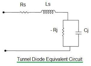
Figure 1: Tunnel Diode Equivalent Circuit
Figure 1 depicts the equivalent circuit. Here’s a breakdown of the components:
- : Diode junction resistance (approximately 100 Ohms)
- : Junction capacitance (in pF)
- : Lead inductance (in nH)
- : Lead resistance/bulk resistance of the semiconductor (few Ohms)
The impedance of the tunnel diode circuit can be expressed as follows:
From the oscillation condition (Re(Z) = 0 and Im(Z) = 0) of the tunnel diode, the following two frequencies are derived: resistive cutoff frequency and self-resonant frequency.
-
Resistive cutoff frequency ():
-
Self-resonant frequency ():
Tunnel Diode Amplifier Circuit
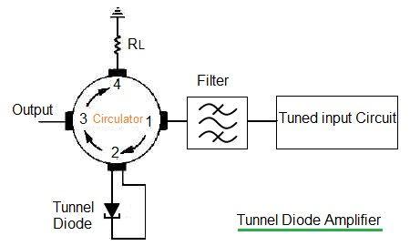
Figure 2: Tunnel Diode Amplifier
Figure 2 depicts a tunnel diode circuit used as an amplifier. Its low noise characteristics make it suitable as the first stage of amplification in communication receivers.
In this circuit, the characteristic impedance of the circulator must be greater than the negative resistance of the tunnel diode. As we know, in a circulator, RF energy travels in only one direction.
As shown in Figure 2, the tunnel diode is connected across tuned input and output circuits. Normally, this circuit produces oscillations when feedback is allowed to reflect back. In this configuration, feedback is prevented, as all the energy is absorbed in the load () due to the circulator.
In this setup, the tunnel diode doesn’t oscillate but amplifies the input signal, producing an amplified output. A bandpass filter is used to provide impedance matching and selection of desired frequencies. The tunnel diode amplifies the signal fed at port-2 and provides an amplified output at port-3.
Tunnel Diode Oscillator Circuit
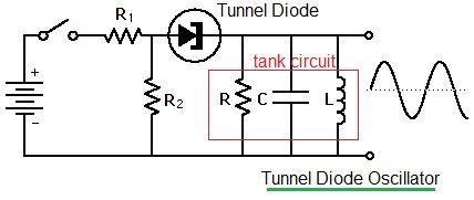
Figure 3: Tunnel Diode Oscillator
Figure 3 depicts a tunnel diode-based oscillator circuit. This circuit can generate microwave frequencies up to 100 GHz.
As shown, the tunnel diode is connected in series with a tank circuit. When power is applied, a surge current produces oscillations in the tank circuit. The values of R and C are chosen to bias the DC operating point at the center of the negative resistance curve of the tunnel diode.
Sustained oscillation results when the magnitude of the negative resistance of the tunnel diode is greater than or equal to the positive resistance of the tank circuit.
Conclusion
The unique negative resistance behavior of tunnel diodes is the key factor that allows them to function as amplifiers and oscillators. Due to limitations in their operational range, careful circuit design and biasing are required to achieve stable and reliable performance.
Advertisement


