Radar Architecture: Block Diagram & Components
Advertisement
Introduction : Radar systems are used in aviation, defense, meteorology or navigation. They rely on a common modular architecture. In this tutorial, we will explore radar architecture block diagram and functions of its components. Moreover we will explore how radar works to detect, locate and track targets.
Radar Architecture working & functions of its components
The fundamental architecture of a typical radar consists of transmitter, receiver, antenna, signal processing chain and display plus ancillary units like duplexers.
Transmit Chain:
- Waveform generator with DAC : It is used to create baseband signal i.e. specific chirp or pulse pattern. DAC converts digital baseband signal to analog signal.
- Mixer and LO (Up conversion) : The signal from DAC is very low in frequency. The RF Mixer takes high frequency LO (Local Oscillator) signal and combines it with baseband signal to up-convert it to target RF (Radio Frequency) eg. 10 GHz for X-Band Radar.
- Power Amplifier (PA) : It takes low power RF signal and boosts it to high power RF signal to counter path loss and other impairments it come across. Modern systems use Gallium Nitride (GaN) based PAs due to its benefits.
- BPF (Band Pass Filter) : It allows specific radar frequencies to pass through while rejecting other frequencies.
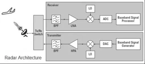 Image Courtesy : Spectrum Control Limited (Microwave Journal eBook Nov. 2025)
Phased Arrays: In modern Active Electronically Scanned Arrays (AESA), the radar doesn’t spin mechanically. Instead, it steers the beam electronically using these two components found in the T/R module viz. phase shifter and digital step attenuator.
- Phase shifter : It is used to change the phase of individual antenna elements. By slightly delaying the signal (i.e. varying phase) at each antenna element, the collective beam can be steered left or right instantly.
- Digital Step Attenuator : This is used to adjust amplitude of the signal. It is used to taper or shape the beam to reduce unwanted side lobes that could create false targets.
T/R Switch or Duplexer: This component rapidly toggles the antenna connection between the Transmitter and the Receiver. When the radar pulses (transmits), the switch connects the PA to the antenna. Nanoseconds later, it switches to the Receiver to listen for the echo. Its primary job is Isolation. It ensures the massive power from the PA doesn’t leak into and destroy the sensitive Receiver components.
Receive Chain:
- Limiter : If strong signal is received, it clips the power to safe level. This prevents LNA fom burning out.
- BPF (Band pass Filter): It passes specific radar frequencies and blocks all the others. It prevents interference from Wi-Fi, bluetooth or other radars.
- LNA (Low Noise Amplifier) : It amplifies weak incoming echo without adding significant noise of its own.
- Mixer and LO (Down conversion) : The received RF signal is higher and are converted back to lower intermediate frequency (IF) to make processing easier by digital processors.
- ADC (Analog to Digital Converter): Finally, analog signal is digitized so the radar software can analyze the time delay (or distance) and frequency shift (speed/doppler).