
NFC Tutorial: Protocol Stack, Working, Frame and Modes
Advertisement
Near Field Communication (NFC) is a short-range wireless communication technology that has revolutionized how devices interact in various industries, from payments to data sharing.
This NFC tutorial guide covers the protocol stack, working principles, frame structure, and different communication modes.
What is NFC (Near Field Communication)?
NFC stands for Near Field Communication. It’s a short-range, low data rate wireless communication technology operating at 13.56 MHz frequency. It’s a contactless mode of communication using electromagnetic waves.
This technology allows two devices housing an NFC chip to communicate for various applications, for example:
- Data communication between smartphones
- Verification of an authenticated person having an NFC ID card at the office by an NFC reader in the door.
- Banking payments using NFC compliant credit cards to enhance security
- Ticket booking at airports
- Automatic running of scheduled features in an NFC phone.
The following table summarizes features of wireless NFC (Near Field Communication) technology.
| Features | NFC (Near Field Communication) |
|---|---|
| Support RF Carrier Frequency | 13.56 MHz |
| Distance | less than 10 cm |
| Data Rate | 106 or 212 or 424 Kbps |
| NFC Network Devices | Tags and Readers, NFC Tag vs Reader |
| NFC Tag Types | Type 1 to 5 |
| Network configuration | peer to peer |
| NFC Network Device Modes | Card Emulation, Reader/Writer, Point to Point (active & passive) |
| Two NFC device communication modes | active-passive or active-active |
| Connection establishment time | Few seconds (approx. less than 0.1 sec) |
| Data Coding Schemes | NRZ-L, Manchester, Modified Miller, |
| Data Modulation Schemes | ASK, BPSK |
| Collision mechanism (i.e. MAC) | Anti-collision support |
| NFC Standards | ISO 14443A/B, ISO 18092, JIS X6319-4 |
Table 1: NFC network features or NFC capability
There are three types of NFC forum specifications viz. NFC-A, NFC-B and NFC-F.
How NFC Works
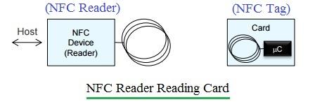
Figure : 1 NFC Network
As mentioned, an NFC network consists of two devices known as the initiator device and the target device.
An NFC tag can be an active or passive device. An NFC reader is always an active device. These devices operate in either active-active or active-passive modes.
In active-active mode, both NFC devices have their own power. In active-passive mode, the passive device derives its power from the received EM waves of the active device.
The basic mode of communication in NFC is half-duplex, where one NFC device transmits while the other receives. This is also referred to as “Listen before Talk.”
One of the two NFC devices will function as an initiator, which first listens on the channel and transmits only when no other signal is present. The Initiator polls other devices that come closer, and the other NFC device, referred to as the target, listens and responds to the initiator as per the requested message.
NFC Network Modes: Card Emulation, Reader/Writer, Point to Point (Peer)
There are three modes in which NFC tags and readers work: Card Emulation, Reader/Writer, and Peer to Peer (or Point to Point), as explained below.
NFC Card Emulation Mode
In this mode, usually an active device reads a passive device.
EXAMPLE #1: ID cards, NFC tags, or NFC-compliant tickets are read by NFC-compliant active readers at offices or railway stations.
EXAMPLE #2: A smartphone acts as a smart card to allow booking tickets or performing online banking transactions or payments using a credit card reader.
Following are the steps involved in card emulation mode:
- Step 1: The NFC reader oscillates at a 13.56 MHz RF field. When the card comes near the RF field, it gets power due to EM (Electro-Magnetic) coupling and connects with the reader.
- Step 2: The reader sends commands using the RF field.
- Step 3: The card responds to the reader as requested.
NFC Reader/Writer Mode
In this mode, one device will be in reading mode, and the other will be in writing mode. They can be either active or passive devices.
- Example #1: Product Authentication
- Example #2: Smart advertising
- Example #3: Device pairing
Following are the steps involved in reader/writer mode:
- Step 1: In read mode, the NFC reader reads NFC tags, either passive or active.
- Step 2: In write mode, one NFC device writes to the other NFC device.
NFC Peer to Peer (Point to Point)
In this mode, data is transmitted from one NFC device to another in ad-hoc or peer-to-peer mode. Any device can become the initiator, and the rest will act as targets to complete the connection establishment.
- Example #1: Smartphone to smartphone communication
- Example #2: Automotive (in-car operation)
- Example #3: Social media applications or games
Following are the steps involved in peer-to-peer mode (active mode):
- Step 1: Both NFC smartphones establish pairing for data communication. Both have power and their own RF fields.
- Step 2: The initiator sends commands by modulating the RF field and switches off the RF field.
- Step 3: The target device responds to the initiator using its own RF field modulation.
NFC Protocol Stack
The figure depicts the protocol stack of NFC in peer to peer mode. As shown, it consists of the application layer, data link layers (logical link control and media access control), and the physical layer.
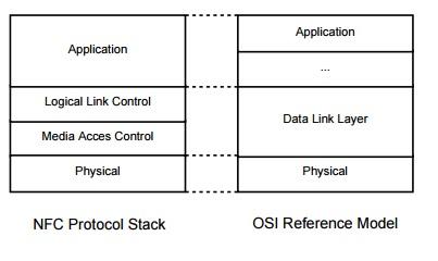
Figure : 2
-
Application Layer: This layer takes care of the format of the data to be exchanged between NFC devices or between the NFC device and tags. This layer contains two components viz. NDEF (NFC Data Exchange Format) and SNEP (Simple NDEF Exchange Protocol). NDEF consists of actual data payload (URL, text, Vcard). SNEP functions as delivery protocol that carries NDEF message in PUT request and GET request frames.
-
Data Link Layer: This layer houses LLCP component which establishes communication between two peer devices. It manages connection and ensures reliable data delivery and handle flow control. This layer takes care of different modes of operation and anti-collision mechanism.
-
Physical Layer: This layer handles radio frequency (13.56 MHz) and electromagnetic induction to establish initial “tap” connection. The NFC physical layer takes care of modulation, coding and RF related parameters such as frequency and power. It is defined in ISO/IEC 18092 (NFCIP-1) standard which specifies communication protocols and interface for NFC devices which supports data rates ranging from 106 kbit/second to 848 kbit/second.
NFC Frame Structure
The NFC frame uses a special encapsulation format referred to as NDEF (NFC Data Exchange Format) which is binary format. Each NFC device transmission is known as a message. One message is composed of one or more records. Each record consists of a header part and a payload part. The header part is made of identifier, length and type fields. The payload contains actual application data (e.g. text content, URI, MIME payload).
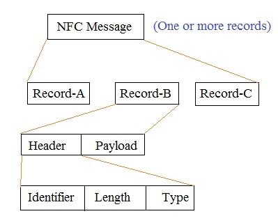
Figure : 3
Payload is variable in size, and content is application specific and related to type of record. For URI record, payload contains web address of the webpage which polling device should open as per request. Text records contain descriptive text and can be added to any type of message.
NDEF Record Header
| Field | Size | Description |
|---|---|---|
| Flags & TNF | 1 Byte | The first byte is bit-packed set of flags and TNF as described below. |
| Type Length | 1 Byte | Specifies the number of octets in the TYPE field. always present. |
| Payload Length | 1 or 4 bytes | Specifies the length of the payload. Either 1 byte or 4 byte long, depending on the SR flag. SR=1 it is 1 byte, SR=0, it is 4 byte. |
| ID_Length | 1 Byte (Optional) | Required if the IL flag is set. Specifies the size of the Payload ID field. It specifies number of octets in the ID field. |
| Payload Type | Variable (Size is defined by type length above) | Required if the Type Length is > 0. Describes the semantic type of payload (e.g. NFC Forum text, URI, MIME type). |
| Payload ID | Variable (Optional) | Present only if IL=1, ID_Length>0. Unique identifier for this record (e.g. link records together or for application use). |
Flags and TNF
Following sub-fields { MB ME CF SR IL TNF (3 bits) } are used at the start of record header.
| Sub-field | Size/Description |
|---|---|
| MB (Message Begin) | 1 bit, indicates start of NDEF message. |
| ME (Message End) | 1 bit, Indicates this is the last record in the message. |
| CF (Chunk Flag) | 1 bit, Indicates the record has chunked payload data. |
| SR (Short Record) | 1 bit, if ‘1’ payload length is 1 byte, if ‘0’ payload length is 4 bytes. |
| IL (ID Length Present) | 1 bit, if ‘1’, an ID_Length field follows. |
| TNF (Type Name Format) | 3 bits, indicates format of the type field. |
TNF (Type Name Format) Key Values
| TNF Value | Meaning |
|---|---|
| 0x00 | Empty record - no payload or type. |
| 0x01 | NFC Forum well known type. |
| 0x02 | MIME media type. |
| 0x03 | Absolute URI. |
| 0x04 | NFC Forum external type. |
| 0x05 | Unknown type. |
| 0x06 | Unchanged - used in chunked payloads. |
| 0x07 | Reserved (not for use). |
Conclusion
NFC technology simplifies wireless communication by utilizing a well structured NFC protocol stack and various operational modes. Its intuitive working principles and frame structure make it ideal for a range of applications, from simple data transfers to complex secure transactions. This NFC tutorial is very useful for beginners who would like to understand how NFC enables secure and efficient data exchange in close proximity.
References for further study
- NFC Data Exchange Format (NDEF) Technical Specification, NFC Forum – detailed layout & field definitions
- Adafruit NFC guide – practical explanation of header flags and fields.
- ISO/IEC 14443 (Type A & B)
- ISO/IEC 18092 / NFCIP-1
- ISO/IEC 15693 (Vicinity cards)
Advertisement


