
TE11 vs TM11 Mode: Understanding the Difference in Waveguides
By RF Wireless Expert Team
Advertisement
This page explains the difference between the TE11 mode and the TM11 mode. Let’s dive into the details!
Cutoff wavelength in a rectangular waveguide is defined by the following formula:
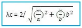
Where:
- ‘m’ = number of half-waves along the broad side dimension
- ‘N’ = number of half-waves along the shorter side
TE11 mode
- In a TE11 mode, there exists one half wave of the electric (E) field in both the broader and shorter dimensions.
- The electric field has no component in the direction of wave propagation (i.e. longitudinal direction).
- TE11 is dominant mode in circular waveguide. It has the lowest cutoff frequency and is the most efficient for signal transmission.
- Applications: Commonly used in microwave and RF systems due to its efficient propagation characteristics.
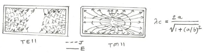
TM11 mode
- Conversely, in a TM11 mode, there exists one half wave of the magnetic (H) field in both the broader and shorter dimensions.
- The magnetic field has no component in the direction of wave propagation.
- TM11 has higher cutoff frequency compared to TE11, making it less efficient for signal transmission.
- Applications: Utilized in certain resonant cavity designs