PWS vs CATR: 5G/6G OTA Testing Methods
Advertisement
Introduction : As wireless technology evolves into 5G mmWave and early 6G, the antennas inside smartphones, IoT devices and base stations are required to be tested using Over the Air (OTA) methods. However, accurately measuring an antenna’s true performance requires the device to be exposed to a “plane wave” which are electromagnetic wave fronts are flat and parallel.
In the real world, achieving a natural plane wave requires placing the device at a massive distance from the transmitter; known as the Fraunhofer distance. Because building football field sized anechoic chambers is impractical and expensive, the industry uses specialized technologies to “trick” the device into experiencing far field conditions within a compact laboratory space. The two primary methods for achieving this are CATR (Compact Antenna Test Range) and PWS (Plane Wave Synthesis).
Compact Antenna Test Range (CATR)
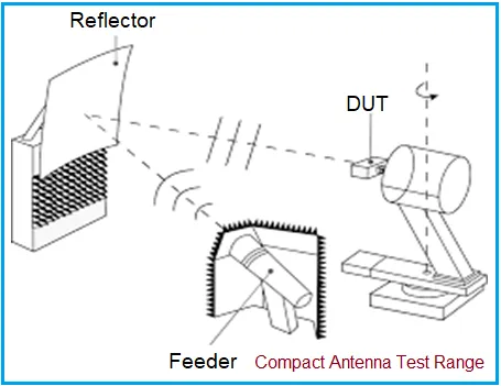
This method relies on the principles of microwave optics and physical geometry. In a CATR setup, a feed antenna (like a corrugated horn) transmits spherical waves toward a highly precise, parabolic reflector (often with rolled edges to prevent signal scattering). When the spherical waves hit the parabolic reflector, they bounce off and are transformed into parallel, uniform plane waves. This creates a specific 3D volume in the chamber known as the “quiet zone,” where the Device Under Test (DUT) is placed. The same is shown in the figure-1 below.
Advantages: Because CATR relies on physical geometry and passive reflectors, it can support extremely wide frequency bandwidths.
Disadvantages: While much smaller than a traditional far field chamber, a CATR still requires a relatively large footprint.
Plane Wave Synthesis (PWS)
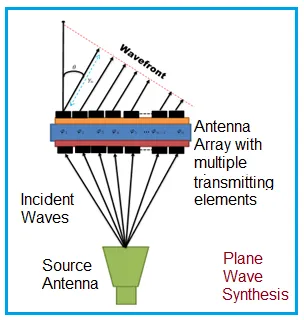
Plane Wave Synthesis (PWS) represents a leap from optical physics to digital signal processing. Instead of using a physical parabolic mirror to flatten the wave, PWS uses a dense, active array of controlled transmitter elements. This is depicted in the following figure-2.
By digitally manipulating the amplitude and phase of the signal at every individual antenna element in the array, the system effectively synthesizes a uniform plane wave electronically. The wave fronts are perfectly aligned by the time they reach the quiet zone just a short distance away.
Advantages: PWS drastically reduces the required spatial footprint of the testing chamber; often shrinking the required space by a factor of 2 to 5 compared to CATR.
Disadvantages: PWS relies on active electronic components such as phase shifters and other beamforming circuitry. Frequency bandwidth is inherently limited by the capabilities of that specific circuitry, making it less broadband than a passive CATR reflector.
Key differences
| Feature | Compact Antenna Test Range (CATR) | Plane Wave Synthesis (PWS) |
|---|---|---|
| Core Technology | Microwave optics and physical geometry. | Digital signal processing and active phased arrays. |
| Wave Transformation Method | Passive; Bounces spherical waves off a precision-machined parabolic reflector to flatten them. | Active; Digitally controls phase and amplitude across an array to electronically synthesize flat waves. |
| Space requirements | Moderate; Requires a range distance of roughly 5x the quiet zone diameter (5 D). | Ultra Compact; Requires a range distance of only 2x the quiet zone diameter (2 D). |
| System Footprint | Larger; requires specific physical angles between the feed horn, reflector, and DUT. | Significantly smaller; reduces spatial footprint by a factor of 2 to 5 compared to CATR. |
| Bandwidth Capability | Excellent (Broadband); Passive reflectors naturally support incredibly wide frequency ranges. | Limited; Bandwidth is restricted by the operational limits of the active beamforming circuitry. |
| Hardware Complexity | High mechanical complexity; requires perfectly machined, heavy reflectors with specialized edges. | High electronic complexity; requires dense arrays of phase shifters and advanced calibration algorithms. |
Summary: For 5G and 6G OTA testing, the choice between CATR and PWS ultimately comes down to a trade off between measurement bandwidth and laboratory real estate. CATR provides unmatched, broadband frequency coverage through passive microwave optics, whereas PWS leverages active digital signal processing to synthesize plane waves, shrinking the required chamber footprint by up to a factor of five.