
CAN Frame Types: Data, Remote, Error & Overload Frames
Advertisement
Introduction : The CAN protocol supports multiple frame types to manage different communication needs. It also ensures that CAN network is fully compliant with CAN standard and resilient under load or fault conditions.
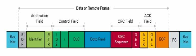
Data Frame
- Purpose : To send actual data such as engine RPM, wheel speed or temperature readings to one or more nodes on the bus.
- Structure : Data frame consists of following fields inside a message.
- Start of Frame (SOF): Indicates beginning of the frame and synchronizes all nodes. It is filled with single dominant bit.
- ID (Identifier) : Can be either 11 bit or 29 bit message identifier (ID).
- RTR (Remote Transmission) : It is set to 0 (Dominant) to signify that it is data frame
- IDE : distinguishes between standard (IDE =0) or extended CAN frame (IDE =1).
- DLC (Data Length Code ) : Specifies how many bytes (0-8) are in the data field.
- Data Field : Actual payload of the message, containing 0 to 8 bytes of data.
- CRC Field : This 16 bit field is used by receivers to verify integrity of the transmitted data frame.
- ACK slot : Transmitting node sends recessive bit in this field. Any node which receives message correctly will assert dominant bit in this field. This action overwrites the recessive bit and confirms the receipt of the message.
- Format: It can be standard data frame (11 bit ID) or extended data frame (29 bit ID).
Remote Frame
- Purpose : It is used to request the transmission of a specific data frame from another node. It triggers another node to send a data frame with specific identifier.
- Structure :
- RTR bit is set to 1 (Recessive). This is how all the nodes know it’s a request and not a data delivery.
- There is NO Data Field. As it is a request, it carries no payload.
- DLC specifies length of the requested data.
- How it works:
- Node-A sends a ‘remote frame’ with ID of 0xf1e and recessive RTR bit.
- Node-B which is configured to respond to requests for ID 0xf1e, sees this frame.
- Node-B then transmits a ‘Data Frame’ with same ID 0xf1e (and a dominant RTR bit), containing the relevant data.
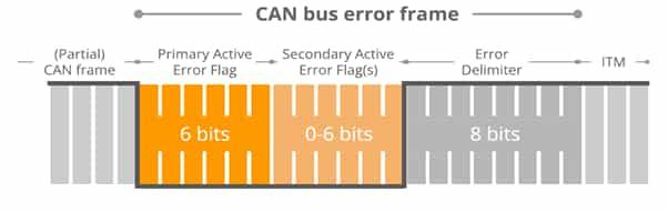
Error Frame
- Purpose: This is a special frame, transmitted by any node that detects a protocol error. Its purpose is to destroy the current, corrupted message on the bus and force all nodes to disregard it. It ensures network wide data integrity by immediately signaling that a fault has occurred.
- Structure: An Error Frame is a unique signal that intentionally violates CAN’s physical layer rules. It consists of two parts viz. error flag and error delimiter.
- Error flag is a sequence of 6 consecutive dominant bits. This violates the “bit-stuffing” rule of CAN (which states that after 5 consecutive bits of the same polarity, a bit of the opposite polarity must be inserted). This violation is an unambiguous signal to all nodes that an error has occurred.
- Error delimiter is a sequence of 8 recessive bits. This provides a pause, allowing the bus to stabilize before any node attempts to re-transmit.
- When is it sent? As soon as any node detects one of the following error type i.e. CRC error, format error, acknowledgement error, bit error or bit-stuffing error.
Overload Frame
- Purpose: To inject a small delay to give a temporarily overwhelmed node (e.g., a slow microcontroller) time to catch up. It is used by a node to request a delay between frames because it is too busy to process the next one. This frame is initiated by receiving node that is overwhelmed.
- Structure: It is structurally identical to an Error Frame, consisting of an Overload Flag (6 dominant bits) and an Overload Delimiter (8 recessive bits).
Key difference between Overload & Error Frame
- An Error Frame can be transmitted at any time an error is detected, interrupting a message mid-transmission.
- An Overload Frame can only be transmitted in the Interframe Space, which is the idle period after a frame has been successfully completed.
Summary: The use of different CAN frames enable the CAN bus to support efficient data transfer, on-demand data requests, robust error handling and proper bus timing.
Advertisement


