IMPATT Diode Calculator: Resonant Frequency and CW Power
Advertisement
This page provides information about an IMPATT diode calculator. The formulas for calculating resonant frequency and CW power are also explained.
EXAMPLE:
-
INPUTS:
- η (Efficiency) = 15%
- Vo (Operating Voltage) = 100 volts
- Io (Operating Current) = 200mA
- Vd (Carrier Drift Velocity) = 2E5
- L (Drift Region Length) = 6 µm
-
OUTPUTS:
- CW Output Power = 3 Watts
- Resonant Frequency = 16.67 GHz
IMPATT Diode Calculator Formulas
The following equations are used in the IMPATT diode calculator:
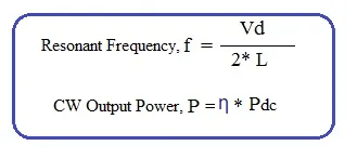
Where:
- f = Resonant Frequency
- P = CW Output Power
- Vd = Carrier Drift Velocity
- L = Drift region length
- η = Efficiency (numeric value)
- Pdc = Operating Power = Max. operating voltage x Max. operating current