Ethernet TCP IP Packet Format and header fields
Advertisement
Introduction : In today’s high-speed digital world, efficient and reliable data communication hinges on understanding how information travels across networks. Whether you’re streaming a video, browsing a website, or syncing files in the cloud, your data moves through multiple layers. The data packets go through the link layer, moving through the network layer and then the transport layer. At each of these layers an essential structure called the header carries metadata that governs routing, addressing, integrity, segmentation and delivery. In this page, we explore in depth the header fields of Ethernet, IP (Internet Protocol) and TCP (Transmission Control Protocol). We will explain the purpose of each field, how the fields interplay across layers.
TCP/IP Packet Structure & header fields
The following table breaks down the fields within a typical TCP/IP packet, including their sizes, types, and descriptions. Following are as per old RFCs.
| No. of bytes | Field type | Description | Header type |
|---|---|---|---|
| 1-6 | DA | Destination address | Ethernet Header |
| 7-12 | SA | Source Address | Ethernet Header |
| 13-14 | Type | Type Field (0x800 - IP, 0x806 - ARP) | Ethernet Header |
| 15 | Ver,IHL | Ver=4, No. of 4 byte words in the header | IP header |
| 16 | Type | Type of Service (typically 0) | IP header |
| 17-18 | T-len | Total length of packet in bytes including IP header | IP header |
| 19-20 | ID | Unique Identification of packet | IP header |
| 21 | Flags | 3 bits (0-DF-MF) DF=0 May fragment, MF=0 last fragment | IP header |
| 21-22 | Offset | Fragment offset in 64 bit blocks | IP header |
| 23 | TTL | Time to live | IP header |
| 24 | Protocol | Upper layer protocol carried in data (TCP/UDP) | IP header |
| 25-26 | Checksum | Checksum of the header | IP header |
| 27-30 | IP SA | IP source address | IP header |
| 31-34 | IP DA | IP destination address | IP header |
| 35-36 | S-port | Source port | TCP header |
| 37-38 | D-port | Destination port | TCP header |
| 39-42 | Seq. Num. | Sequence Number | TCP header |
| 43-46 | ACK | Acknowledgement number | TCP header |
| 47 | Len (Data Offset) | 4 bit size of TCP header in 4 byte words | TCP header |
| 47-48 | Reserved | 6 bits not used | TCP header |
| 48 | Flags | UAPRSF (U=Urgent, A=Ack, P=Push, R=Reset, S=Sync, F=Fin) | TCP header |
| 49-50 | Window | TCP Window (for flow control) | TCP header |
| 51-52 | Checksum | Checksum for header and data | TCP header |
| 53-54 | Urgent* | Urgent pointer | TCP header |
| 55 to N | DATA | TCP Data | Data Payload |
| N+1 | FCS | CRC (4 byte) | Ethernet Header |
- After “*Urgent Pointer” Options field will follow as per latest RFC of TCP header ( RFC 9293).
- If DF (Don’t Fragment) = 1 and the packet encounters a link with too small an MTU, the packet must be dropped rather than fragmented
- When fragmentation occurs: MF (More Fragments) = 1 for all fragments except the last one, which has MF = 0 This ‘MF’ bit, when set to 0, indicates that this packet is not followed by more fragments of the same original datagram — i.e., it’s either the only fragment or the last fragment.
Example (FTP upload with fize size of 2020 bytes)
Assume there are two hosts, i.e. client (Host#1) and server (Host#2) communicating using FTP protocol. As per Old RFC, we have IP header of 20 bytes size and TCP header of 20 bytes size. We are left with (1500-40)=1460 bytes of payload data in packet-1. Rest of the payload data i.e. 2020-1460 = 560 bytes are carried by packet#2. Following table mentions actual values for this example for both the packets.
- On a standard Ethernet network, the MTU (Maximum Transmission Unit) at the IP layer is typically 1500 bytes.
Ethernet Header
| Fields | Packet-1 (Client->Server , first data chunk) | Packet-2 (Client->Server, second & final data chunk) |
|---|---|---|
| Destination address | 66:77:88:99:AA:BB | 66:77:88:99:AA:BB |
| Source address | 00:11:22:33:44:55 | 00:11:22:33:44:55 |
| Type Field | 0x0800 | 0x0800 |
IP Header
| Fields | Packet-1 | Packet-2 |
|---|---|---|
| IP version (4 bits) | 4 | 4 |
| Header length (4bits) (IHL) | 5 (20 Bytes) | 5 |
| Type of Service | 0 | 0 |
| Total Length | 1500 bytes (20 bytes IP header, 20 bytes tcp header, 1460 tcp data) | 600 bytes (20 + 20 + 560 ) |
| Identification | 0x1A2B | 0x1A2C |
| Flags (DF,MF) | DF=1, MF = 1 | DF=1, MF = 0 |
| Fragment Offset | 0 | 0 |
| Time to Live | 64 | 64 |
| Protocol | 6 | 6 |
| Header Checksum | computed | Computed and placed |
| Source IP | 10.0.0.1 | 10.0.0.1 |
| Destination IP | 172.16.0.10 | 172.16.0.10 |
TCP Header
| Fields | Packet-1 | Packet-2 |
|---|---|---|
| Source Port | 49152 | 49152 |
| Destination Port | 21 | 21 |
| Sequence Number | 100000 (initial assumed) | 101460 |
| Ack number | 200000 | 200000 |
| Data Offset | 5 (indicates 20 bytes) | 5 |
| Flags (SYN, ACK, FIN, RST, PSH, URG) | ASK=1, PSH=1 | ACK=1, PSH = 1 |
| Window size | 65535 | 65535 |
| Checksum | Calculated and placed | Calculated & placed |
| Urgent Pointer | 0 | 0 |
| Options | None | None |
During Connection Establishment (Three-way Handshake)
Following flags are set during initial tcp/ip connection establishment process.
- Client → Server: SYN = 1, ACK = 0, other flag bits (FIN, RST, PSH, URG) = 0
- Server → Client: SYN = 1, ACK = 1, other flag bits (FIN, RST, PSH, URG) = 0
- Client → Server: ACK = 1, other flag bits (SYN, FIN, RST, PSH, URG) = 0
For both the example, packets during data phase following are the setting of 6 flags.
- Packet 1 (data): SYN=0, ACK=1, FIN=0, RST=0, PSH=1, URG=0
- Packet 2 (data): SYN=0, ACK=1, FIN=0, RST=0, PSH=1, URG=0
If the receiver sends an ACK only (no data) back to the sender, flags are set as follows.
- ACK packet: SYN=0, ACK=1, FIN=0, RST=0, PSH=0, URG=0
TCP Header as defined in RFC9293
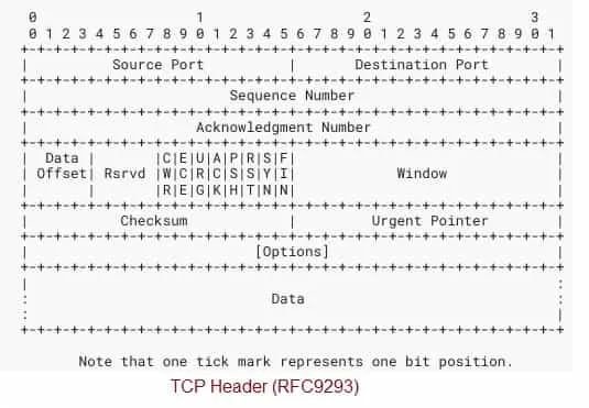 Image Courtesy (IETF) : RFC 9293
Following are the changed fields compared to previous RFCs.
Data Offset (4 bits) :
-
Indicates the size of the TCP header in 32‐bit words. In other words, it tells where the data payload begins. Minimum value is 5 (i.e. 20 bytes) for a header with no options.
-
Example : If data offset = 5, then header is 5 × 32 bits = 160 bits = 20 bytes.
-
Because of this field, the header may include optional fields (so header length can vary).
Options (variable length, optional):
- Immediately follows the fixed header fields. Because the Data Offset field sets the header length, options may or may not be present and may be of varying length.
- Options must align on 32‐bit word boundaries (padding may be required) so that the header ends at a 32‐bit boundary.
- The maximum header length (with options) is typically 60 bytes. For which, data offset maximum value can be 15 (15 × 4 = 60 bytes).
Conclusion: From the source and destination MAC addresses in the Ethernet header, to the version, protocol identifier and TTL in the IP header, and onward to the ports, sequence and acknowledgment numbers in the TCP header; these fields together ensure that data is delivered, in order, intact and to the right place.