CAN Protocol Stack : Physical & Data Link Layer
Advertisement
Introduction: The CAN (Controller Area Network) protocol is a foundational communication standard widely used in automotive, industrial and embedded systems. ISO 11898 standard defines two layers of the OSI model for CAN bus architecture viz. physical and data link layer.
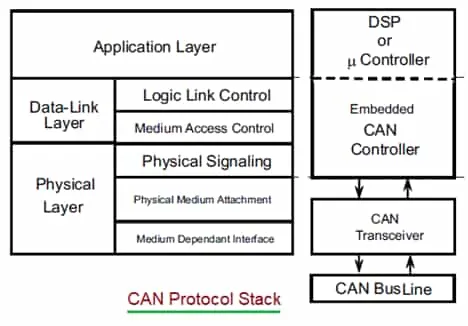
The physical layer defines wiring, signalling and bus topology. The data link layer governs frame structure, arbitration, error detection and fault handling. Together these layers enable reliable, real time data exchange in hostile electrical environments and resource constrained systems. Application Layer provides the upper level communication functions to the CAN protocol stack. These functions may be implemented by system software developer or handled by higher layer protocol such as the vendor independent CANopen protocol.
CAN Physical Layer Overview
It is the basic hardware required for a CAN network as per ISO 11898 electrical specifications. It’s main function is to convert 1’s and 0’s into electrical pulses leaving a node, then back again for a CAN message entering a node. Following are major functions of CAN Physical layer.
- Determines bus topology e.g. multi-point serial bus and twisted pair wiring as mentioned.
- Specifies voltage levels i.e. dominant and recessive bits.
- Handles encoding / decoding of bits (i.e., how logical “0” and “1” map to physical voltage states).
- Defines electrical interface characteristics for transceivers (driver/receiver behaviour).
- Enables collision detection and wired-AND behaviour: when multiple nodes drive the bus, a dominant state (bit “0”) overrides recessive (“1”)
- Supports different physical layer variants, such as high speed CAN, low speed fault tolerant CAN, and single wire CAN
- Provides electromagnetic noise immunity, because differential signalling cancels out common mode interference
CAN Bus Topology
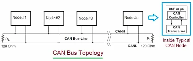
As shown in the figure, typical CAN node contains controller and transceiver. CAN controller is the hardware that implements data link layer of the CAN protocol. Most of the microcontrollers now-a-days houses CAN controller. CAN transceivers implement Physical (i.e. PHY) layer, usually external to the device. The CAN node is also referred as an ECU (Engine Control Unit) in automotive terminology.
CAN bus uses differential pair of wires, twisted to prevent EMI (Electro-Magnetic Interference). These wires are terminated by 120 Ohm resistors on both the ends. The wires are designated as CAN_H and CAN_L. It uses non-return to zero (NRZ) signaling in which there are two states to represent logical-0 and logical-1.
- Dominant Voltage = “0” bit
- Recessive Voltage = “1” bit
Binary data are represented as per difference between voltage on CAN_H and CAN_L wires.
- Dominant is when Vd >= 0.9 V
- Recessive is when Vd <= 0.5 V
CAN Waveform
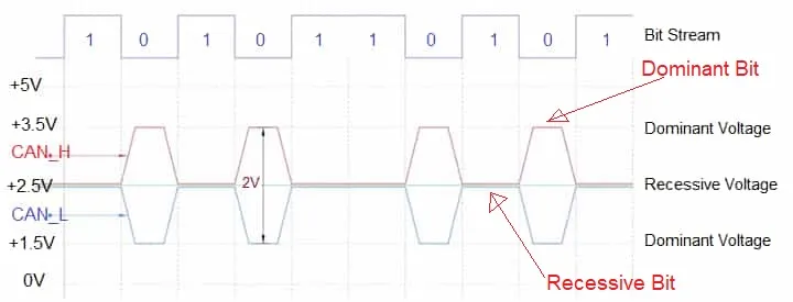
As shown in this waveform, binary data are mapped as per differential voltage described above.
Binary 0 (Dominant Bit) :
- CAN-H ~ 3.5V
- CAN-L ~ 1.5V
- Differential voltage ~ 2V
- About 2 volt differential is taken as dominant bit
Binary 1 (Recessive Bit) :
- CAN-H ~ 2.5 V
- CAN-L ~ 2.5 V
- Differential voltage ~ 0V
- No significant voltage difference is taken as recessive bit.
Physical Layer variants
- High Speed CAN : Defined by CAN standard, part ISO 11898-2. It uses two wire balanced signaling scheme.
- Low Speed CAN : Defined by CAN standard, part ISO 11898-3. It also uses two wire balanced signaling scheme for lower bus speeds.
- SAE J2411: Defines signal wire + ground physical layer.
- Proprietary CAN physical layers.
Length Vs Rate in CAN
| Bus Length (Meters) | Signaling Rate (Mbps) |
|---|---|
| 40 | 1 |
| 100 | 0.5 |
| 200 | 0.25 |
| 500 | 0.10 |
| 1000 | 0.05 |
Cables
As mentioned, CAN bus lines almost always use a shielded twisted pair cable for the two signal wires (CAN H and CAN L), to ensure consistent impedance and reject electromagnetic noise. The characteristic impedance of the cable should be about 120 Ohm (acceptable range between 108 to 132 Ohm). Often a second twisted pair or a ground/shield conductor is included to provide a stable reference (CAN GND), especially in longer or industrial strength installations.
CAN Line Terminations & Connectors
As defined in ISO standard, CAN bus must be terminated by 120 Ohm resistor on both the ends of the bus. The termination helps in following.
- It removes signal reflections at both the ends.
- It ensures the bus gets correct DC voltage levels.
Following are common connector types used in CAN connections for various applications.
- 9-pin DSUB connector
- 5-pin Mini-C and/or Micro-C connector
- 6-pin Deutch connector
CAN Data Link Layer
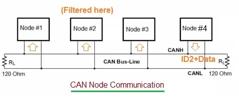
This layer is responsible for transferring messages from node to the network without errors. After sending the message, it waits for ack from receivers. Following diagram illustrate communication between two nodes. For example there are four nodes connected to the CAN bus. Node#4 intends to send data to the Node#2. In order to do this, Node#4 initiates transmission of CAN frame with (ID2+Data) on the bus. As CAN works based on broadcast mode, the (ID2+Data) is broadcasted to all the nodes connected on CAN network. Hence, the data is received by all the nodes, but only Node#2 filters the frame as its ID (Identifier) address matches with the ID contained in the frame i.e. ID2.
Following are the functions of CAN data link layer.
- It performs frame encapsulation/de-encapsulation of upper layer data.
- MAC/Arbitration : Decides which node can transmit by non-destructive bitwise arbitration based on message priority ID.
- Detects different types of errors e.g. CRC check, bit-stuffing errors, form errors, ack errors.
- Error signalling : When an error is detected, nodes broadcast an error frame to inform all the other nodes.
- Acknowledgement : Upon successful reception of the frame, at least one receiver must send a dominant bit in ACK slot.
- Bit Stuffing and destuffing : Inserting bits to maintain synchronization (after five consecutive bits of same level) and removing them on reception.
- Serialization / deserialization: Converting frames into a serial bit stream for transmission, and back into frames upon reception.
- Filtering : Each CAN node can decide whether to accept or ignore a frame based on its identifier (message filtering).
- Manages overload conditions by transmitting overload frames.
- Retransmit frames who were flagged with errors.
CAN Frame : Standard and Extended
- CAN_Standard_Frame : {SOF, ID, RTR, R0, R1, DLC, Data, CRC, ACK, EOF, IFS }
- CAN_Extended_Frame : {SOF, ID_1, SRR, IDE, ID_2, RTR, R0, R1, DLC, Data, CRC, ACK, EOF, IFS }
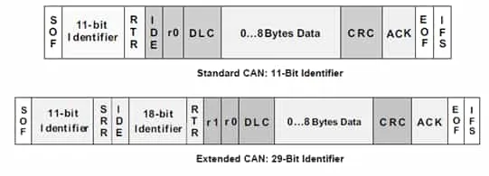
Following are the fields of CAN classic frame with their sizes and usage.
- SOF (Start of Frame) : Size - 1 bit, Indicates intension of node to transmit by using dominant ‘0’.
- ID (Identifier) : Size - 11 bit (CAN Classic) or 29 bit (CAN extended), used as frame identifier, lower the value, higher is the priority
- RTR (Remote Transmission Request) : Size - 1 bit , value in this field indicates whether node is transmitting itself (RTR=0) or requesting other dedicated node to transmit (RTR=1)
- R0 & R1 : Size - 2 bits , R1 is used as IDE (Identifier Extension Bit) where as R0 is used as FDF (Flexible Data Rate Format) bit. IDE = 0 means 11 bit ID is used in CAN standard frame. IDE = 1 means 29 bit is used as identifier. Flexible Data Rate Format = recessive (1) indicates that the frame is a CAN-FD frame. FDF bit with dominant (0) signifies a classical CAN frame.
- DLC (Data Length Code) : Size - 4 bits, indicates size of the data payload carried in a CAN frame following this field.
- Data : Size - 0 to 64 bits, this field carry data payload with maximum size up to 64 bits in classic CAN and extended CAN frames. CAN-FD supports maximum of 64 bytes. CAN-XL supports maximum of 2048 bytes.
- CRC (Cyclic Redundancy Check): Size - 16 bits, used for error detection to ensure data integrity.
- ACK (Acknowledgement) field : Size - 2 bits (ACK slot & ACK delimiter), ACK slot = dominant (0) by transmitting node indicates that it has received the frame and CRC correctly. A single recessive (1) bit follows the ACK slot.
- EOF (End of Frame): Size - 7 bits , Seven recessive (‘1’) bits mark the end of the frame.
In addition to above, following fields are added in CAN extended frame.
- ID_1 and ID_2 together form 29 bit identifier.
- SRR (Substitute Remote Request) : Size-1 bit , This bit replaces RTR field of standard frame. SRR bit is always sent as recessive (logic-1) in extended frames.
- IDE (Identifier Extension) : Size-1 bit , This bit indicates whether the frame uses the standard 11-bit identifier (IDE = dominant/“0”) or the extended 29-bit identifier (IDE = recessive/“1”).
CAN Evolutions
Following table compares different CAN evolutions such as classical CAN, CAN extended, CAN-FD and CAN-XL with respect to maximum data rate, maximum payload and other parameters.
| Feature | Classical CAN (2.0A) | CAN extended (2.0B) | CAN FD (Flexible Data Rate) | CAN XL (Extra Large) |
|---|---|---|---|---|
| Identifier length | 11 bit | 29 bit | 11 bit or 29 bit | 11 bit XL-ID (New Format) |
| Max. Data Rate | ~ 1 Mbps | ~ 1 Mbps | 5 to 8 Mbps | 20 to 30 Mbps |
| Max. Payload | 8 bytes | 8 bytes | 64 bytes | 2048 bytes |
| Year of introduction | 1990s | 1995 | 2012 | 2020s |
| Use Case | Basic Automotive Control | Larger networks needing more IDs | High speed data, ECU flashing etc. | High Bandwidth ADAS, Zonal Architecture |
Summary
Together, physical and data link layers of CAN protocol are well suited for distributed real time control because the bus is noise immune, fault tolerant, low cost and efficient with minimal wiring. It also offers deterministic message delivery (due to arbitration & priority) and robust error handling. The framework is engineered for reliability in demanding systems such as in-vehicle network, industrial controller or embedded module.
References
Refer following standard published by ISO on its website www.iso.org for more detailed information.
- ISO 11898-1 Part 1: Data link layer and physical signalling. (defines the CAN data-link, framing, identifiers (11-bit & 29-bit), arbitration, error handling).
- ISO 11898-2 Part 2: High-speed physical medium attachment (HS-PMA) sublayer. (high-speed physical layer for up to ~1 Mbps).
- ISO 11898-3 Part 3: Low-speed, fault-tolerant, medium-dependent interface. (fault-tolerant / low-speed physical layer).