RF
RF802.11ad Tutorial: WiGig Technology Basics
Advertisement
IEEE 802.11ad, also known as WiGig, is a wireless communication standard that operates in the 60 GHz frequency band. It’s designed to deliver multi-gigabit data rates, with theoretical speeds up to 7 Gbps over short distances. The high frequency enables ultra-fast data transmission, making it ideal for applications like wireless docking stations, HD video streaming, and VR/AR experiences. However, due to its limited range and poor obstacle penetration, 802.11ad is primarily suited for indoor environments and point-to-point communication.
This tutorial on 802.11ad (60 GHz) technology covers WiGig basics, channels, frame types, modulation-code rate, spectrum mask, 11ad physical layer, and conformance testing.
802.11ad Channels
The following table outlines the country-wide frequency allocations for 802.11ad.
WLAN-11ad Country Wide Frequency Allocations
| Country/Region | Frequency range |
|---|---|
| US and Canada | 57.05 to 64.00 GHz |
| European Union | 57.00 to 66.00 GHz |
| South Korea | 57.00 to 64.00 GHz |
| Japan | 57.00 to 66.00 GHz |
| Australia | 59.40 to 62.90 GHz |
| China | 59.00 to 64.00 GHz |
The 802.11ad standard utilizes four channels: Channel-1, Channel-2, Channel-3, and Channel-4. Table 2 specifies the frequency range and RF center frequency for each of these channels. Each channel has a bandwidth of approximately 2.16 GHz.
WLAN-11ad Channels
| 802.11ad channel number | RF Center frequency | RF Frequency range |
|---|---|---|
| Channel-1 | 58.32 GHz | 57.24 to 59.40 GHz |
| Channel-2 | 60.48 GHz | 59.40 to 61.56 GHz |
| Channel-3 | 62.64 GHz | 61.56 to 63.72 GHz |
| Channel-4 | 64.80 GHz | 63.72 to 65.88 GHz |
WLAN 802.11ad Frame Types
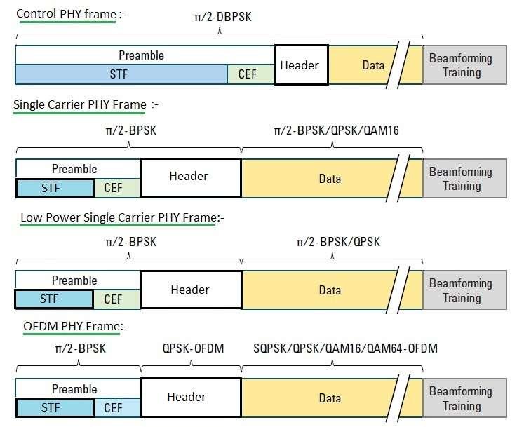
Figure 1: 802.11ad Frame Types
Figure 1 illustrates the different physical layer frame formats. There are four distinct PHY modes: Control, Single Carrier, Low Power Single Carrier, and OFDM.
An 802.11ad frame consists of three primary parts: a preamble, a header, and a payload.
- Preamble: A known data pattern used for front-end synchronization at the receiver, covering time, frequency, and channel correction.
- Header: Contains information necessary to decode the payload, including the modulation and coding scheme used.
- Payload: The actual data being transmitted.
Here’s a breakdown of the header contents for each PHY mode:
Control Packet Header
- 1 bit – Diff. detector initialization
- 4 bits – Scrambler initialization
- 10 bits – Length
- 1 bit – Packet type
- 5 bits – Training length
- 1 bit – Turnaround
- 2 bits – Reserved
- 16 bits – HCS
Single Carrier Header
- 7 bits – Scrambler initialization
- 5 bits – MCS
- 18 bits – Length
- 1 bit – Additional PPDU
- 1 bit – Packet type
- 5 bits – Training length
- 1 bit – Aggregation
- 1 bit – Beam tracking request
- 4 bits – Last RSSI
- 1 bit – Turnaround
- 4 bits – Reserved
- 16 bits – HCS
OFDM Header
- 7 bits – Scrambler initialization
- 5 bits – MCS
- 18 bits – Length
- 1 bit – Additional PPDU
- 1 bit – Packet type
- 5 bits – Training length
- 1 bit – Aggregation
- 1 bit – Beam tracking request
- 1 bit – Tone pairing type
- 1 bit – DTP indicator
- 4 bits – Last RSSI
- 1 bit – Turnaround
- 2 bits – Reserved
- 16 bits – HCS
STF stands for Short Training Field and CEF stands for Channel Estimation Field.
802.11ad Modulation-Code Rate
Tables 3 to 5 provide information about the modulation code rates for the different physical layer modes. This information is mapped to an MCS index, which is included in the header of the 802.11ad packet. This index indicates the modulation and code rate of the data payload or control information.
Modulation code rate for control PHY
| MCS Index | Modulation | Code rate | Data rate |
|---|---|---|---|
| MCS-0 | DBPSK | 1/2 | 27.5 Mbps |
Modulation code rate for Single Carrier PHY
| MCS Index | Modulation | N | CBPS | Repetition | Code rate |
|---|---|---|---|---|---|
| MCS-1 | π/2 BPSK | 1 | 2 | 1/2 | 385 |
| MCS-2 | π/2 BPSK | 1 | 1 | 1/2 | 770 |
| MCS-3 | π/2 BPSK | 1 | 1 | 5/8 | 962.5 |
| MCS-4 | π/2 BPSK | 1 | 1 | 3/4 | 1155 |
| MCS-5 | π/2 BPSK | 1 | 1 | 13/16 | 1251.25 |
| MCS-6 | π/2 QPSK | 2 | 1 | 1/2 | 1540 |
| MCS-7 | π/2 QPSK | 2 | 1 | 5/8 | 1925 |
| MCS-8 | π/2 QPSK | 2 | 1 | 3/4 | 2310 |
| MCS-9 | π/2 QPSK | 2 | 1 | 13/16 | 2502.5 |
| MCS-10 | π/2 16QAM | 4 | 1 | 1/2 | 3080 |
| MCS-11 | π/2 16QAM | 4 | 1 | 5/8 | 3850 |
| MCS-12 | π/2 16QAM | 4 | 1 | 3/4 | 4620 |
Modulation code rate for OFDM PHY
| MCS Index | Modulation | Code rate | N | BPSC | N CBPS | N DBPS |
|---|---|---|---|---|---|---|
| MCS-13 | SQPSK | 1/2 | 1 | 336 | 168 | 693.00 |
| MCS-14 | SQPSK | 5/8 | 1 | 336 | 210 | 866.25 |
| MCS-15 | QPSK | 1/2 | 2 | 672 | 336 | 1386.00 |
| MCS-16 | QPSK | 5/8 | 2 | 672 | 420 | 1732.50 |
| MCS-17 | QPSK | 3/4 | 2 | 672 | 504 | 2079.00 |
| MCS-18 | 16-QAM | 1/2 | 4 | 1344 | 672 | 2772.00 |
| MCS-19 | 16-QAM | 5/8 | 4 | 1344 | 840 | 3465.00 |
| MCS-20 | 16-QAM | 3/4 | 4 | 1344 | 1008 | 4158.00 |
| MCS-21 | 16-QAM | 13/16 | 4 | 1344 | 1092 | 4504.50 |
| MCS-22 | 64-QAM | 5/8 | 6 | 2016 | 1260 | 5197.50 |
| MCS-23 | 64-QAM | 3/4 | 6 | 2016 | 1512 | 6237.00 |
| MCS-24 | 64-QAM | 13/16 | 6 | 2016 | 1638 | 6756.75 |
Modulation code rate for Low Power Single carrier(SC) PHY
| MCS Index | Modulation | Effective Code rate | Coding Scheme | N | CPB |
|---|---|---|---|---|---|
| MCS-25 | π/2 BPSK | 13/28 | RS(224,208)+Block code(16,8) | 392 | 626 |
| MCS-26 | π/2 BPSK | 13/21 | RS(224,208)+Block code(12,8) | 392 | 834 |
| MCS-27 | π/2 BPSK | 52/63 | RS(224,208)+SPC(9,8) | 392 | 1112 |
| MCS-28 | π/2 QPSK | 13/28 | RS(224,208)+Block code(16,8) | 392 | 1251 |
| MCS-29 | π/2 QPSK | 13/21 | RS(224,208)+Block code(12,8) | 392 | 1668 |
| MCS-30 | π/2 QPSK | 52/63 | RS(224,208)+SPC(9,8) | 392 | 2224 |
| MCS-31 | π/2 QPSK | 13/14 | RS(224,208)+Block code(8,8) | 392 | 2503 |
WLAN 802.11ad Spectrum Mask
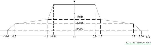
Figure 2: WLAN 802.11ad Spectrum Mask
Figure 2 shows the 802.11ad spectrum mask. The X-axis represents frequency, and the Y-axis represents decibels relative to the signal level at band center (dBr). This spectrum mask is approved by the ITU-WPA5.
This 802.11ad spectrum mask differs from the masks used in lower frequency wireless standards. The breakpoints in the mask are at -17 dBr. This applies to both Single Carrier and OFDM modulation types. Out-of-band rejections are kept high to simplify RF circuit designs for these WiGig 60 GHz transmitters. Typically, 10 dBm is used as the maximum allowed transmit power, although this varies slightly by country.
The transmit spectrum mask is measured on data packets greater than 10 µs without the training fields. These 11d spectrum mask measurements are carried out with a Resolution Bandwidth (RBW) of 1 MHz. The nominal bandwidth used is 1830.47 MHz for OFDM PHY and 1760 MHz for Single Carrier PHY.
Conclusion
802.11ad (60 GHz) technology significantly enhances wireless performance by offering extremely high data rates over short distances, providing a key solution for bandwidth-intensive applications. While its limited range and sensitivity to obstacles restrict its use to specific environments, the technology’s potential for high-speed wireless connectivity makes it ideal for applications in home networks, entertainment systems, and enterprise environments where high throughput and low latency are essential. As wireless demand grows, 802.11ad complements other WiFi technologies to offer versatile connectivity options for different use cases.
This 802.11ad tutorial is very useful for beginners who would like to start learning WiGig basics.
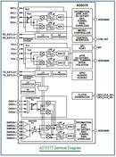
WLAN 802.11ad Physical Layer
The 802.11ad Physical layer helps encode the MAC layer data packet suitable to be transmitted over the 802.11ad air interface. There are four different physical layers used in the transmitter, so the physical layer modules vary in each.
In general, the physical layer is composed of a scrambler, an LDPC encoder or RS encoder used as FEC techniques, modulation, interleaver, guard insertion, spectrum shaping, and RF up conversion. IFFT is included in the OFDM Phy version.
Advertisement