LTE-M Tutorial: Network Architecture, Frequency Bands, and Stack
Advertisement
Introduction
LTE-M, short for Long Term Evolution for Machine-Type Communications and also known as LTE Cat-M1, is a Low Power Wide Area (LPWA) technology standardized by 3GPP as part of the Release 13 specifications. It’s specifically designed to support IoT (Internet of Things) applications that demand low power consumption, extended battery life, and wide coverage.
LTE-M is a cost-effective solution that leverages existing LTE networks, making it ideal for deploying IoT devices without the need for entirely new infrastructure. LTE-M, along with NB-IoT, are two LPWA technologies designed and developed for IoT applications to transmit/receive small amounts of data using lower bandwidth at low costs.
The evolution of LTE-M started with the need for a specialized network that could handle the massive influx of IoT devices anticipated in the coming years. Traditional LTE networks were not optimized for small data packets, low power consumption, or deep indoor coverage, which are critical for many IoT use cases such as smart metering, asset tracking, and industrial automation.
As a result, 3GPP introduced LTE-M to address these limitations, providing a reliable, scalable, and efficient solution for connecting billions of IoT devices globally.
This LTE-M tutorial covers basic features, LTE-M network architecture, protocol stack layers, frame structure, channel types, a comparison with traditional LTE, its benefits, and more.
LTE-M Technology Features
There are different categories of LTE-M devices viz. Cat-0, Cat-M1, and Cat-M2 as per different 3GPP releases. LTE-M Cat-0, Cat-M1, and Cat-M2 follow 3GPP TS 36 series of rel.12, rel.13, and rel.14 respectively.
The following are the features supported in LTE Cat-M1 devices. It has been deployed in a number of countries across the world by various operators in different frequency bands. Some of the countries are Mexico, United States, Canada, North America, Sri Lanka, UAE, Japan, Singapore, New Zealand, Switzerland, Australia, and so on.
LTE-M uses bands 1, 2, 3, 4, 5, 7, 8, 11, 12, 13, 18, 19, 20, 26, 27, 28, 31, 39, 41 under release 13 and bands 25 and 40 under release 14.
| LTE-M Cat-M1 Features | Description |
|---|---|
| Bandwidth | 1.4 MHz (Maximum 6 PRBS are allocated in DL/UL equivalent to 1.08 MHz) |
| Peak Data Rate (DL/UL) | 1 Mbps |
| Duplex modes | HD-FDD, FD-FDD, TDD |
| Number of receive antennas | 1 |
| Transmit power | 20 dBm |
| Advanced power saving modes | PSM, eDRX |
| Modulation (Highest) | 16-QAM |
| Coding scheme (DL/UL) | Turbo code |
| Spatial Layers (Max. in DL/UL) | 1 |
| Maximum TBS (DL/UL) | 1000 bits |
| CE Modes | Mode-A (Mandatory), Mode-B (Optional) |
| LTE-M Device Categories | Cat-0, Cat-M1, Cat-M2 |
LTE-M focuses on three main features in comparison to NB-IoT as follows:
- Higher uplink/downlink speed of up to 1 Mbps.
- VoLTE support for voice calls.
- Mobility support for devices in movement.
LTE Cat-M1 Frequency Bands
LTE-M operates on the same frequency bands as standard LTE networks, allowing seamless integration and coverage in existing LTE infrastructure. However, the frequency bands used for LTE-M vary by region and operator. Some of the commonly used bands for LTE-M are as follows:
| Region | LTE Cat-M1 frequency bands (MHz) |
|---|---|
| North America | Band 2 (1900), Band 4 (1700/2100), Band 12 (700) |
| Europe | Band 3 (1800), Band 8 (900), Band 20 (800) |
| Asia | Band 1 (2100), Band 3 (1800), Band 8 (900) |
| Worldwide | Band 13 (700), Band 28 (700), Band 39 (1900) |
These bands ensure that LTE-M devices can operate in diverse environments, providing broad geographic coverage and reliable connectivity.
LTE-M Network Architecture
The architecture of LTE-M network is similar to the standard LTE architecture but includes modifications to optimize performance for IoT applications. The figure depicts LTE-M architecture in a roaming scenario. Both the user plane and control plane are shown, which are used for the transport of data and control information. The key components are as follows:
- User Equipment (UE): Devices such as sensors, meters, and tracking units that connect to the LTE-M network.
- eNodeB: The LTE base station that communicates with the UE and manages radio resources. LTE-M operates using the same eNodeBs as standard LTE, minimizing deployment costs.
- Evolved Packet Core (EPC): The core network that handles data routing, mobility management, and authentication. EPC components include the MME (Mobility Management Entity), SGW (Serving Gateway), and PGW (Packet Gateway).
- Application Server: An external server where IoT applications are hosted, processing data transmitted by LTE-M devices.
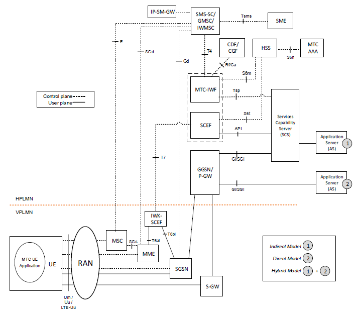
LTE-M introduces new features in the RAN (Radio Access Network) to enhance its suitability for IoT applications as follows:
- Enhanced coverage: LTE-M provides up to 15 dB of additional link budget, enabling deep indoor coverage.
- Reduced complexity: Reduced bandwidth and a simplified protocol stack lower the complexity of the devices.
- Power-saving features: LTE-M supports Power Saving Mode (PSM) and eDRX (extended Discontinuous Reception) to significantly extend battery life.
LTE-M Protocol Stack Layers
LTE-M stack is designed to provide reliable and efficient data transmission over the LTE Cat-M1 network. It handles data processing and communication between User Equipment (UE) and the LTE network. The stack is divided into the user plane and the control plane.
The user plane consists of PDCP, RLC, MAC, and PHY. The control plane consists of Non-Access Stratum (NAS), Radio Resource Control (RRC), and Packet Data Convergence Protocol (PDCP), RLC, MAC, and PHY Layer.
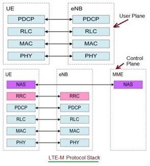
The figure depicts LTE-M Protocol Stack layers. Both user plane and control plane protocol layers are shown in the figure.
LTE-M Frame Structure
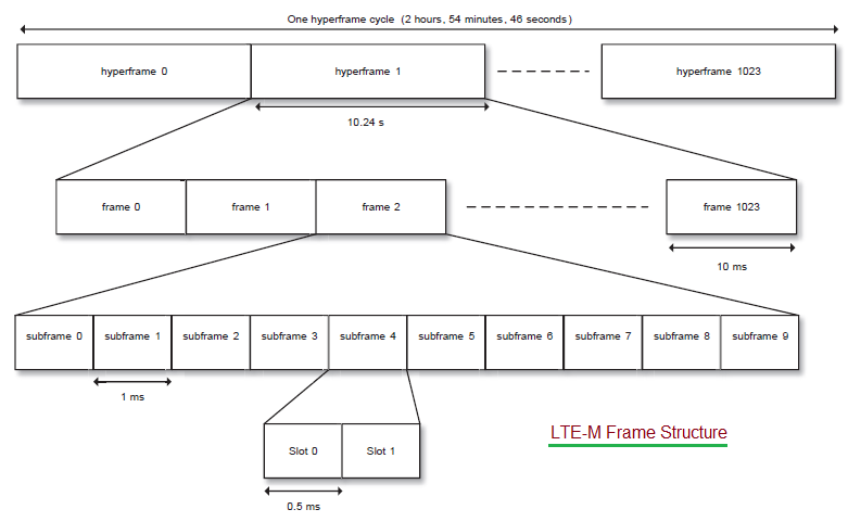
The figure depicts the LTE-M frame structure, similar to LTE technology. As shown, one hyperframe cycle consists of 1024 hyperframes. Each hyperframe consists of 1024 frames.
One frame consists of 10 subframes. One subframe consists of two slots, each having a 0.5ms duration. Each slot occupies either 7 symbols (for normal CP) and 6 symbols (for extended CP). Each subframe is uniquely identified by H-SFN (range 0-1024), SFN (range 0-1024), and SN (range 0-9).
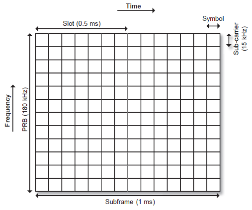
The smallest resource unit used by an LTE-M device is one PRB pair mapped over two slots. One PRB pair spans 12 subcarriers with 15 KHz subcarrier spacing. This gives a total bandwidth of 180 KHz for 12 subcarriers. The figure depicts 12 subcarriers over 14 symbols for normal CP operation used as a PRB pair in LTE-M.
LTE-M Channel Types
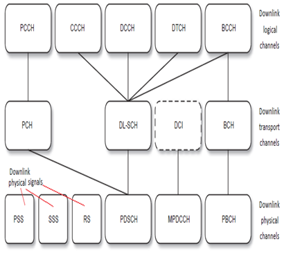
LTE-M supports a set of downlink and uplink channels and signals. The mapping between logical channels, transport channels, and physical channels is also shown. As mentioned, PSS, SSS, and RS are used as downlink signals, whereas PDSCH, MPDCCH, and PBCH are used as downlink channels.
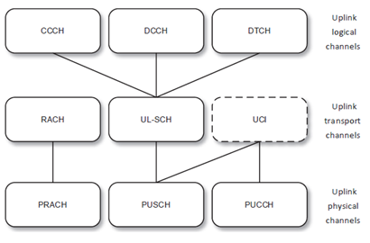
PRACH, PUSCH, and PUCCH are used as uplink channels, as shown in the figure. RS and DMRS are used as reference signals in the uplink.
LTE-M RRC Resume Procedure
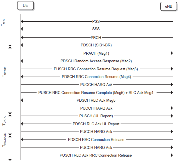
The figure depicts the LTE-M RRC Resume procedure.
Advantages of LTE-M
The following are the benefits of LTE-M for IoT deployments, making it a popular choice for a variety of use cases.
- Power-saving features such as PSM and eDRX can extend battery life to over 10 years for low-power devices, making LTE-M suitable for battery-operated sensors and meters.
- With reduced complexity and lower bandwidth requirements, LTE-M devices are more cost-effective compared to traditional LTE devices.
- LTE-M offers up to 15 dB additional link budget, enabling reliable operation in challenging environments such as underground locations or deep indoors.
- LTE-M operates on existing LTE infrastructure, minimizing deployment costs and allowing for faster rollouts.
- With support for millions of devices per square kilometer, LTE-M is scalable to support large-scale IoT deployments.
- While limited, LTE-M provides adequate mobility for applications like asset tracking and fleet management.
- As a 3GPP standardized technology, LTE-M ensures interoperability across different vendors and networks.
Difference Between LTE-M and LTE
Although LTE-M and LTE share the same infrastructure and frequency bands, there are several key differences between the two technologies as follows:
| Parameters | LTE-M 3GPP Cat-M1 | Standard LTE |
|---|---|---|
| Frequency Bands | Operates on existing LTE frequency bands | Uses standard LTE bands |
| Bandwidth | 1.4 MHz | Up to 20 MHz |
| Data Rate | Up to 1 Mbps | Up to 100 Mbps |
| Power Consumption | Lower due to PSM and eDRX | Higher |
| Device Complexity | Reduced complexity for lower cost devices | Higher complexity |
| Mobility Support | Limited mobility | Full mobility support |
| Latency | 10-15 ms | < 10 ms |
| Coverage | Enhanced coverage, up to 15 dB gain | Standard LTE coverage |
| Application Use Cases | IoT applications (e.g., metering, tracking) | General broadband and mobile services |
Conclusion
LTE-M is a key enabler for IoT applications, providing a low-cost, power-efficient, and scalable solution for connecting a wide range of devices. Its ability to leverage existing LTE infrastructure makes it a compelling choice for network operators and enterprises seeking to deploy IoT solutions without substantial new investments.
With features such as extended battery life, improved coverage, and lower complexity, LTE-M is poised to support a diverse range of IoT use cases, from smart cities to industrial automation.
As the adoption of IoT continues to grow, LTE-M will play a crucial role in bridging the gap between traditional LTE networks and future 5G deployments, offering a robust and reliable connectivity option for billions of devices worldwide.
Advertisement
 RF
RF


