1-Wire Communication Protocol: Single Wire Interface Overview
Advertisement
The 1-Wire interface protocol, developed by Dallas Semiconductor (now part of Maxim Integrated), uses a single wire for transmitting and receiving data, along with a ground connection. Its simplicity and cost-efficiency make it suitable for a variety of applications. Let’s explore the one-wire protocol along with its features, advantages, and disadvantages.
The single-wire interface uses a master-slave configuration where a single slave or multiple slaves interface with a single master on the bus. It’s generally used for low-power and low-speed communication. Data communication is byte-wise, with the Least Significant Bit (LSB) transmitted first.
Key Features of the One-Wire Protocol
Here are some of the key features of the one-wire interface protocol:
- It uses a single data line, eliminating the need for a separate clock signal. Two wires are still required (data and GND).
- A clock signal isn’t required, as slave devices use an internal clock synchronized with the signal from the master device.
- It employs a half-duplex communication mechanism.
- It offers less hardware complexity but requires more software complexity for algorithm implementation.
- Due to reduced wiring, it’s a cheaper and more economical interface protocol.
- It uses a supply voltage between 2.8V and 5.25V.
- It uses a 64-bit device addressing scheme.
- Multiple slaves are supported in multi-drop mode.
- It supports a data rate of 16.3 Kbps in standard mode and 163 kbps in overdrive mode.
- It has low power consumption.
1-Wire Interface Bus Requirements
Figure 1 shows a simple one-wire interface configuration between a single master and multiple slaves in multi-drop mode. The following interface bus requirements and power modes are supported.
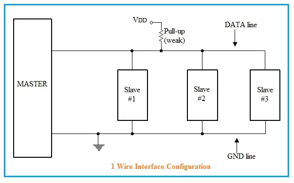
Bus Requirement:
All output pins should be connected with a weak pull-up resistor and must be open drain. When any device drives the bus low, the bus will be in a low state. Data transfer occurs between two devices when the others are in an IDLE state.
The device utilizes external power. Therefore, it requires pull-up values of 10K or higher for lower data rates with shorter trace lengths. It requires a pull-up of less than 1K for higher data rates with long trace lengths.
Power Modes:
Slave devices support two power modes:
- External mode: Slaves requiring more power use this mode. A power pin on the slave device interfaces with an external supply.
- Parasitic mode: Slaves derive power from the data line. When the bus is idle, it uses a capacitor to store energy and is pulled up by a weak pull-up resistor.
One-Wire Protocol Signaling Modes
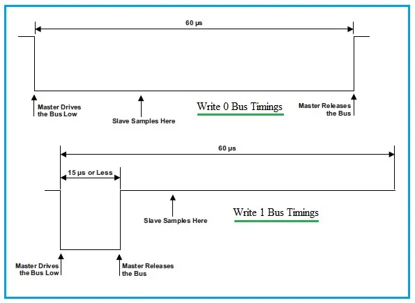
Figure 2 shows the write 0/1 bit signaling diagram. To write a 0 bit, drive the bus low for about 60µs. To write a 1 bit, drive the bus low for less than 15 µs (typically 6µs). Release the bus until 60 µs after the falling edge.
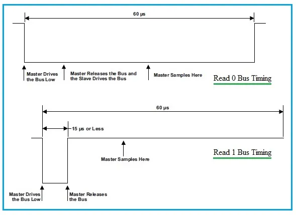
Figure 3 depicts the read 0/1 bit signaling diagram. Read bit signaling is the same as the write 1 signaling diagram. However, here the master will read instead of writing. The logic for reading is to drive the bus low from 1µs to 15µs. The bus is sampled after the falling edge, usually at 15 µs, to read the bit from the slave.
Advantages of 1-Wire Protocol
-
Simplicity:
- Single Wire: Requires only one data line and a ground line, reducing wiring complexity and cost.
- Ease of Implementation: The protocol is relatively simple to implement and integrate into various systems.
-
Cost Effective:
- Reduced Wiring Costs: Fewer wires mean lower material and installation costs.
- Low-Cost Devices: Many 1-Wire devices are designed to be inexpensive, making the protocol suitable for large-scale applications.
-
Flexible Power Options:
- Parasite Power Mode: Devices can operate without an external power supply, which is useful in battery-operated or remote applications.
-
Multiple Devices:
- Multiple 1-Wire devices can be connected to the same bus, allowing for easy expansion and scalability.
-
Robustness:
- Built-in error-checking mechanisms help ensure data integrity and reliability.
Disadvantages of 1-Wire Protocol
-
Limited Data Rate:
- The 1-Wire protocol has relatively low data transfer rates compared to other communication protocols, which may not be suitable for high-speed applications.
-
Limited Distance:
- The communication range is limited, and performance can degrade over longer distances or with multiple devices connected to the same bus.
-
Power Constraints:
- In parasite power mode, power constraints can limit the number of devices on the bus and affect performance. For some applications, external power may be required.
-
Complex Timing Requirements:
- The protocol requires precise timing for communication, which can make implementation challenging in some systems.
-
Device Addressing:
- While each 1-Wire device has a unique address, managing and organizing a large number of devices on the same bus can become complex.
Summary
The 1-Wire protocol is a useful and cost-effective solution for simple communication and sensor networks, especially where wiring simplicity and low cost are priorities. However, it has limitations in terms of data rate, distance, and power constraints, which should be considered when designing systems that use this protocol.