 RF
RFWaveguide Bends and Flanges: Types and Applications
Advertisement
Waveguide bends and flanges are essential for routing and connecting waveguides in RF systems. This article examines their designs, types, and practical applications in optimizing signal transmission across complex setups.
Waveguide Bends
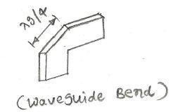
The figure below depicts a 45-degree waveguide bend. As the bands are separated by , the reflections are canceled by each other. This creates a waveguide band without any reflections.
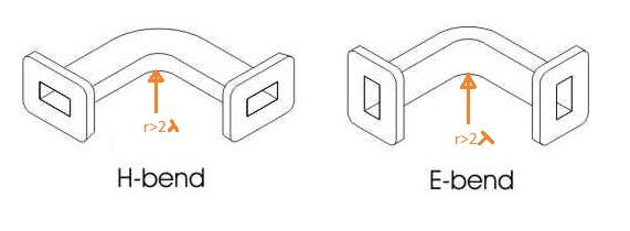
The two types of waveguide bends, viz. E-bend and H-bend, are shown in the figure below. As shown, the radius is greater than . This prevents reflections within the bend length.
Waveguide Twists or Flanges
The figure below depicts a waveguide twist or flange.
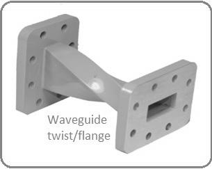
Following are the typical specifications of the waveguide twists or flanges to be considered while selecting one for your needs:
- Flange type: C-Cover/ G-Groove, CHOKE, CMR, CPR (F, G)
- Twist angle: 90 degrees, 45 degrees
- Frequency of operation or waveguide size
- Twist Plane: Left-hand, Right-hand
- Insertion Loss: As low as possible (about 0.2 dB)
- VSWR: As low as possible
Types of Waveguide Bends
Waveguide bends are used to alter the direction of waveguide systems while minimizing signal loss and distortion. The types include the following:
- E-Plane Bends: Bends where the electric field (E-field) lies in the plane of the bend.
- H-Plane Bends: Bends where the magnetic field (H-field) lies in the plane of the bend.
- Mitered Bends: Comprise a sharp 90-degree angle with a mitered cut to reduce reflections and losses.
- Twists (Rotational Bends): Gradually rotate the waveguide to align different polarizations or orientations.
Types of Waveguide Flanges
Waveguide flanges connect waveguide sections or components and ensure mechanical stability and signal continuity. The types include the following:
- Rectangular Flanges: Standard flanges used with rectangular waveguides.
- Circular Flanges: Used with circular waveguides, designed to accommodate specific waveguide dimensions.
- Grooved Flanges: Flanges with grooves to accommodate gaskets or O-rings for better sealing.
- Cover Flanges: Simplest type of flange with no choke or sealing groove.
- Choke Flanges: Designed to reduce leakage by introducing a quarter-wavelength choke near the waveguide junction.
Applications
Waveguide flanges and bends are often used together in RF and microwave systems to create efficient and reliable signal pathways. Bends help route waveguides through complex geometries, such as tight spaces or around obstacles, while maintaining signal integrity.
Flanges provide secure mechanical connections between waveguide sections or components, ensuring proper alignment and minimal signal leakage. Together, they are commonly applied in radar systems, satellite communication setups, and high-frequency testing environments, enabling precise signal transmission in intricate layouts while accommodating varying environmental and operational demands.
Waveguide Component Manufacturers
- www.dowkey.com
- www.flann.com
- www.meslmicrowave.com
- www.sectormicrowave.com
- General Atomics, www.ga.com
Conclusion
Understanding waveguide bends and flanges aids in designing efficient RF systems. Their correct implementation ensures seamless wave propagation and system reliability.
Advertisement


