Half-Wave vs. Full-Wave Rectifiers: Key Differences
Advertisement
This article clarifies the differences between half-wave and full-wave rectifiers. As you know, many devices require a DC power supply, which is often derived from the AC mains. The process of converting AC to DC is called rectification, and the circuit responsible for this is called a rectifier.
There are two main types of rectifiers, distinguished by how they handle the AC input: half-wave rectifiers and full-wave rectifiers.
Half-Wave Rectifier

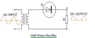
The diagram above illustrates a basic half-wave rectifier circuit. For practical purposes, a load resistor (R) is used to represent the electronic equipment being powered.
During the forward bias condition (the positive half of the AC input cycle), the diode (D) conducts, allowing a pulse of current to flow. This current generates a voltage across the resistor R, and the voltage approximately matches the input voltage if the diode’s forward resistance is negligible compared to the resistance of R.
During the reverse bias condition (the negative half of the AC input cycle), the diode (D) is reverse biased. This blocks current flow, resulting in virtually no current in the circuit and zero voltage across R. Essentially, only half of the AC waveform is used.
Full-Wave Rectifier

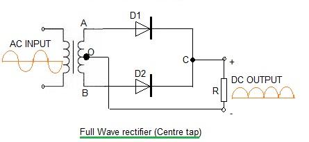
The full-wave rectifier, specifically the center-tapped type shown above, uses both halves of the AC input voltage to produce current pulses. Let’s break down how this works:
- First Half-Cycle: Diode D1 is forward biased (allowing current flow), while diode D2 is reverse biased (blocking current). D1 supplies the current to the output.
- Second Half-Cycle: Diode D1 is now reverse biased, and diode D2 becomes forward biased. D2 takes over and provides current to the output.
In effect, both the positive and negative halves of the AC waveform are utilized to produce a pulsating DC output.
Advertisement
 RF
RF


