Standard vs. Extended CAN Frame Format
Advertisement
This article compares the standard CAN (Controller Area Network) frame format with the extended CAN frame format. It details the various fields used in each structure.
Standard CAN Frame Format
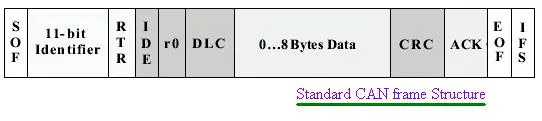
Figure 1: Standard CAN Frame Structure
Table 1 describes the fields used in the standard CAN frame format, which utilizes an 11-bit identifier.
Table 1: Standard CAN Frame Format Fields
| Fields | Description |
|---|---|
| SOF | Start of Frame: A single dominant bit marking the beginning of a message. It’s used to synchronize nodes on the CAN bus. |
| Identifier | An 11-bit binary value that establishes the message’s priority. A lower value indicates a higher priority. |
| RTR | Remote Transmission Request: A dominant bit when a node requires information from another remote node. All nodes receive the request and the reply. The specific node processes the request based on the identifier and transmits the reply. |
| IDE | Identifier Extension: Indicates that a standard CAN frame is being transmitted without extension. |
| r0 | Reserved for future use. |
| DLC | Data Length Code: A 4-bit field indicating the number of bytes to be transmitted over the CAN bus. |
| Data | Contains up to 64 bits of application data. |
| CRC | Cyclic Redundancy Check: A 16-bit field used for error detection. It holds a checksum for the application data preceding it. |
| ACK | Acknowledgement: A 2-bit field. The first bit is the ACK bit, and the second is a delimiter. Each node uses this to show the integrity of its data. A node receiving a correct message overwrites this bit in the original received message with a dominant bit to indicate that an error-free message has been transmitted. A node receiving an erroneous message leaves this bit as recessive. It discards the message and prompts the sending node to re-transmit the message after re-arbitration. |
| EOF | End of Frame: A 7-bit field that marks the end of the CAN frame or message. |
| IFS | Interframe Space: A 7-bit field that represents the time required by the controller to move the correctly received frame to its proper position in the message buffer area. |
Extended CAN Frame Format
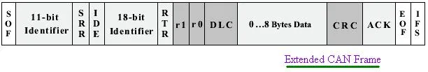
Figure 2: Extended CAN Frame Structure
Table 2 describes the fields used in the extended CAN frame format, which uses a 29-bit identifier.
Table 2: Extended CAN Frame Format Fields
| Fields | Description |
|---|---|
| SRR | Substitute Remote Request: This bit replaces the RTR bit of the standard CAN message as a placeholder in this extended CAN format. |
| IDE | Functions as a recessive bit in identifier extension. It indicates that more identifier bits follow. An 18-bit extension follows the IDE. |
| r1 | An additional reserved bit for future use. |