 RF
RFReflection and Transmission Coefficients Explained
Advertisement
This article explains the definitions and formulas for reflection and transmission coefficients, which are important concepts when dealing with transmission lines.
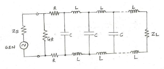
Transmission lines, fundamental for transporting RF energy, are characterized by three basic components: Resistance (R), Inductance (L), and Capacitance (C). The following figure illustrates this:
Examples of transmission lines include:
- Parallel Line
- Gas Filled Coaxial line
- Coaxial line (standard)
- Coaxial Line (Air Articulated dielectric)
- Parallel Line (Shielded)
- Double shielded coaxial Line
- Microstrip line
Let’s delve into the reflection and transmission coefficients themselves.
Reflection Coefficient
The reflection coefficient quantifies the ratio of the reflected wave’s amplitude to the incident wave’s amplitude. More precisely, it’s the ratio of the reflected voltage wave amplitude () to the incident voltage wave amplitude ().
Mathematically, the reflection coefficient () in terms of impedances is:
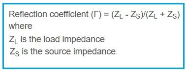
Here, (or ) represents the characteristic impedance of the transmission line, which is calculated as:
where:
- is the resistance per unit length
- is the inductance per unit length
- is the conductance per unit length
- is the capacitance per unit length
- is the angular frequency ()
- is the imaginary unit
Transmission Coefficient
The transmission coefficient, conversely, gauges the amplitude of the transmitted wave relative to the amplitude of the incident wave. It’s defined as the ratio of the transmitted voltage wave amplitude () to the incident voltage wave amplitude ().
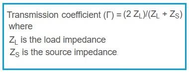
The transmission coefficient () formula, expressed in terms of impedances, is:
Advertisement


