Rectangular vs. Circular Waveguides: Key Differences
Advertisement
Waveguides are crucial in RF and microwave communication, efficiently guiding electromagnetic waves. Rectangular and circular waveguides offer unique advantages for specific applications. This guide explores the differences between them in terms of structure, operating frequency, mode propagation, and applications, helping you make an informed choice. Both waveguide types are metal hollow structures designed to guide EM waves. Their shapes define them as either rectangular or circular. Both behave much like a High Pass Filter and are passive microwave devices.
Rectangular Waveguide
A rectangular waveguide is a type of transmission line with a rectangular cross-section, widely used in RF and microwave systems. It supports electromagnetic wave propagation with minimal loss, typically in the dominant mode. Rectangular waveguides are popular due to their simple design, ease of manufacturing, and high efficiency at specific frequencies. They are commonly employed in radar, satellite communication, and industrial heating applications, where precise signal control and low attenuation are critical.
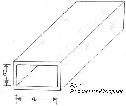
Figure depicting a Rectangular waveguide with broad and narrow dimensions.
The cutoff wavelength equation for a rectangular waveguide is defined below:
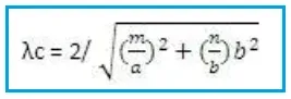
Where:
- = number of half-waves along the broad side dimension
- = number of half-waves along the shorter side
The following table lists cutoff wavelengths and cutoff frequencies for common modes in a rectangular waveguide.
| Mode | Cutoff Wavelength () | Cutoff Frequency () |
|---|---|---|
| , =broad dimension | ||
| , | ||
Circular Waveguide
This waveguide features a cylindrical cross-section, offering unique advantages such as rotational symmetry and support for multiple polarizations. It operates predominantly in the mode and is often chosen for applications requiring high power handling or specific mode propagation characteristics. Circular waveguides are widely used in radar systems, rotating joints, and industrial applications where smooth internal surfaces help minimize signal losses. However, their complex manufacturing process and mode degeneracy can be challenging for certain designs.
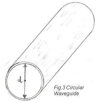
Figure depicting a Circular waveguide.
The cutoff frequency equation for a circular waveguide is:
Where:
- is the speed of light within the waveguide
- is the radius of the circular cross-section
The dominant mode in a rectangular waveguide is , and in a circular waveguide, it is . Rectangular to circular waveguide transitions convert the dominant mode of a rectangular waveguide to the dominant mode of a circular waveguide and vice versa.
The following table shows cutoff wavelengths and frequencies for various common modes in a circular waveguide.
| Mode | Cutoff Wavelength | Cutoff Frequency |
|---|---|---|
| , =diameter of the waveguide | ||
Difference Between Rectangular and Circular Waveguides
| Aspect | Rectangular Waveguide | Circular Waveguide |
|---|---|---|
| Shape | Rectangular cross-section | Circular cross-section |
| Mode of Propagation | Dominant mode is | Dominant mode is |
| Cutoff Frequency | Lower cutoff frequency | Higher cutoff frequency |
| Power Handling | Suitable for lower to moderate power | Better for high power applications |
| Losses | Higher loss due to sharper corners | Lower loss due to smoother internal surface |
| Manufacturing | Easier and less expensive | More complex and costlier |
| Mode Degeneracy | Modes are distinct with no degeneracy | Higher likelihood of mode degeneracy |
| Field Distribution | Fields are concentrated at edges | Fields are evenly distributed |
| Rotational Symmetry | No rotational symmetry | Rotationally symmetric |
| Polarization | Supports single polarization per mode | Supports multiple polarizations |
Conclusion
Understanding the differences between rectangular and circular waveguides is essential for selecting the right one for your RF application. While rectangular waveguides are widely used due to their simplicity and versatility, circular waveguides are advantageous in applications requiring specific mode propagation or rotational symmetry. Evaluate your requirements to determine the most suitable option for your system.