Filter Terms: Shape Factor, Selectivity, Bandwidth & Quality Factor
Advertisement
Filters are essential in signal processing, and understanding terms like shape factor, selectivity, bandwidth, and quality factor is crucial for effective design. These parameters define a filter’s performance and help engineers optimize signal clarity and system efficiency.
We’ll also cover frequency range, attenuation, insertion loss, isolation, passband, stopband, ripple, and group delay.
RF Filter Terminologies
The following table outlines useful RF filter terms.
| RF Filter terminologies or terms | Description |
|---|---|
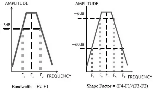
| Bandwidth | Frequency range around the center frequency over which the filter can be used efficiently. Frequencies above and below the center frequency at which the response falls down by 3 dB with reference to the center frequency indicate the limits of the filter bandwidth. |
| Frequency Range | The range of frequencies over which the filter is useful for any application. |
| Shape Factor | It indicates the selectivity of the filter. It is the ratio of the filter’s response at 60 dB to the response at 6 dB attenuation. The shape factor can be expressed as . A lower shape factor means a steeper response of the RF filter. |
| Selectivity | It is a measure of the filter’s capabilities to pass or reject specific frequencies relative to the center frequency. It’s expressed as the loss through the filter that occurs at some specific difference from the filter’s center frequency. For example, the selectivity of a cavity resonator with a center frequency of 150 MHz equals “15 dB down” at a frequency of “1MHz above or below” the center frequency. |
| Attenuation | The amplitude or magnitude loss incurred to the signal once it passes through the RF filter. |
| Insertion loss | This is the same as attenuation. It is the loss of signal power when it travels through the RF filter. |
| Isolation | This refers to the separation of one signal from another in order to prevent any undesired interaction between them. |
| Q-factor | It is a measure of the selectivity of the resonant circuit. The Q-factor is described as the ratio of stored versus lost energy per oscillator cycle. |
| Passband | The region in the frequency response of the RF filter through which the signal passes unattenuated. |
| Stopband | The region in the frequency response of the RF filter through which the signal will be attenuated as per the designed attenuation value. This is the band which stops i.e., attenuates the signal. |
| Ripple | The variation in the insertion loss of the filter in the passband response. The difference between the maximum and minimum attenuation is taken as ripple. |
| Group Delay | It is measured in seconds. It is defined as the propagation delay time of the envelope of an AM modulated signal when it passes through the RF filter. |
Conclusion
Mastering filter parameters such as shape factor, selectivity, bandwidth, and quality factor is key to designing effective signal processing systems, ensuring optimal performance.