RF Detector Circuit as Envelope Peak Detector: Working & Applications
Advertisement
RF detector circuits play a crucial role in RF communication systems by demodulating signals. One widely used configuration is the envelope peak detector. This guide explores how these circuits work, their design principles, and their importance in extracting amplitude information from modulated signals.
The most common RF detector is a diode detector. It is used to sample the amplitude of the input RF signals. These detectors work as simple rectifiers which sample the RF peak while charging a capacitance to hold the peak voltage and discharging the capacitance across the load slowly. Hence it is also known as a peak detector.
Schottky diodes are used as broadband sensors with a frequency range up to 50 GHz. The RF detector curve will usually have three regions: square law, linear, and saturation.
-
Square Law Region: Exists at low RF input levels where the output is proportional to the square of the input amplitude.
-
Linear Region: When the input level reaches about 1V, the curve will be linear.
-
Saturation Region: Reached when the input level becomes larger.
Let’s understand the RF detector used as an AM demodulator. As we know, a demodulator is the circuit that converts and recovers the modulating signal from the modulated signal input.
RF Detector Circuit as AM Demodulator
 RF detector circuit
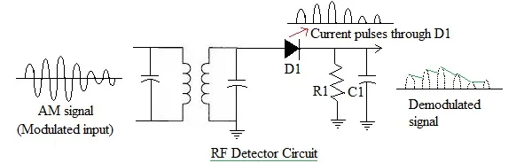
The RF detector circuit used as an AM demodulator is shown in the figure above. As shown, the AM signal is transformer-coupled to a basic half-wave rectifier circuit made of diode D1 and resistor R1.
The diode conducts only when positive half cycles of the AM signal are subjected to the RF detector circuit. During the negative half cycles, the diode gets reverse biased. This results in no current flow. Hence, the voltage across R1 is due to positive pulses only whose amplitude varies with the modulating signal.
In order to retrieve the original modulating signal, a capacitor is connected across resistor R1. The value of this capacitor is carefully chosen so that it has a very low impedance at the carrier frequency and high impedance at the modulating signal frequency. This results in filtering of the carrier frequency signal. Hence, only the original modulating frequency signal will be available at the output.
In order to make this circuit work effectively, the time constant of C and R1 is chosen to be long compared to the period of the RF carrier signal.
As explained, this diode detector circuit recovers the envelope of the Amplitude Modulated signal, so the RF detector circuit is referred to as an envelope detector.
Conclusion
Envelope peak detector circuits are fundamental to RF communication systems, enabling efficient demodulation and amplitude signal detection. A thorough understanding of their working principles aids in designing reliable RF systems for diverse applications.