What are Filter Shape Factor and Bandwidth : Formula & Definitions
Advertisement
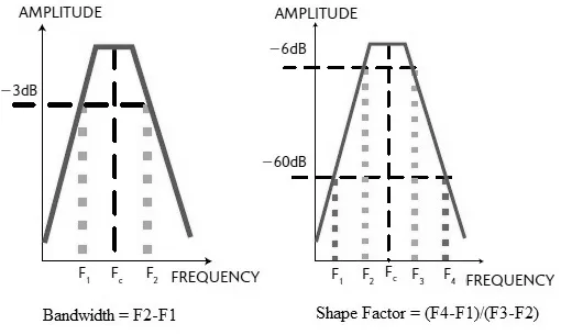
In RF engineering, filter bandwidth is the range of frequencies that a filter allows to pass with minimal attenuation, typically measured between the 3dB cutoff points. The filter shape factor is the ratio of the stopband bandwidth to the passband bandwidth. It defines the steepness of the filter’s roll-off, indicating how sharply it transitions from passing to blocking signals.
The filter shape factor and bandwidth are fundamental metrics in signal filtering.
Shape Factor
-
It indicates the selectivity of the filter.
-
It is the ratio of the filter’s response at 60 dB to the response at 6 dB attenuation, as shown in the figure.
-
The RF Filter shape factor can be expressed by the following equation:
RF Filter Shape Factor =
-
The lower the value of the shape factor, the steeper the response of the RF filter.
Bandwidth
-
The frequency range around the center frequency over which the filter can be used efficiently and effectively is known as the bandwidth.
-
Frequencies above and below the center frequency at which the response falls down by 3 dB with reference to the center frequency indicate the upper and lower limits of the filter bandwidth.
-
The RF Filter Bandwidth can be expressed by the following equation:
Bandwidth =
Here, is the center frequency.
Summary
Understanding filter bandwidth and shape factor is crucial for designing efficient RF systems that require precise frequency isolation. A lower shape factor indicates a sharper filter response, ensuring superior rejection of unwanted adjacent channel interference.