LVDT vs RVDT Sensors: Key Differences Explained
Advertisement
This article clarifies the differences between LVDT (Linear Variable Differential Transformer) and RVDT (Rotary Variable Differential Transformer) sensors. Both are used for position or displacement sensing.
Key Merits of Both LVDT and RVDT:
- Non-contact Operation: Minimal friction, reducing wear and resistive forces.
- Negligible Hysteresis: Both magnetic and mechanical hysteresis are very low.
- Low Output Impedance: Makes them less susceptible to loading effects.
- Noise Immunity: Low susceptibility to noise and interferences.
- Robust Construction: Solid and durable design.
- High Resolution: Infinitesimal resolution is achievable.
LVDT (Linear Variable Differential Transformer)
LVDT sensors use electromagnetic induction to measure linear displacement.
Electromagnetic induction methods are used to sense position and displacement. The movement of an object alters the magnetic flux coupling between two coils, which is then converted into a voltage signal. Variable-inductance sensors use a non-magnetized ferromagnetic medium to alter the reluctance (magnetic resistance) of the flux path; these are known as variable-reluctance transducers.
A multi-induction transducer typically contains two coils: a primary and a secondary. The primary coil is excited with an AC signal, which induces a steady AC voltage in the secondary coil. The amplitude of the induced voltage depends on the flux coupling between the coils. There are two techniques for changing this coupling:
- Movement of a Ferromagnetic Object: Moving an object made of ferromagnetic material within the flux path changes the path’s reluctance, altering the coupling between the coils. This principle underlies the operation of LVDT, RVDT, and mutual inductance proximity sensors.
- Physical Movement of a Coil: Physically moving one coil relative to another.
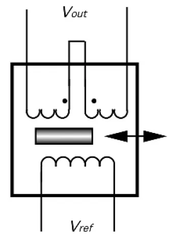
The LVDT operates as a transformer with a mechanically actuated core. The primary coil is driven by a stable sine wave (excitation signal) to eliminate error-related harmonics. This induces an AC signal in the secondary coils, which are connected in opposite phase.
A ferromagnetic core is inserted coaxially into the cylindrical opening without physically touching the coils. When the core is centered, the secondary output signals cancel each other out, resulting in no output voltage.
Moving the core away from the central position unbalances the induced magnetic flux ratio between the secondaries, creating an output voltage. The degree of flux coupling depends on the axial position of the core. In the linear operating region, the amplitude of the induced voltage is proportional to the core displacement. Therefore, voltage can be used to measure displacement.
The LVDT provides both the direction and magnitude of the displacement. The direction is determined by the phase angle between the primary (reference) voltage and the secondary voltage. A stable oscillator generates the excitation voltage.
To accurately measure transient motions, the oscillator frequency must be at least 10 times higher than the highest significant frequency of the movement. For slow-changing processes, the stable oscillator can be replaced by coupling to a power line frequency of 60 or 50 Hz.
One common application for LVDT sensors is in gauge heads, which are used in tool inspection and gauging equipment. In these applications, the inner core of the LVDT is spring-loaded to return the measuring head to a preset reference position.
RVDT (Rotary Variable Differential Transformer)
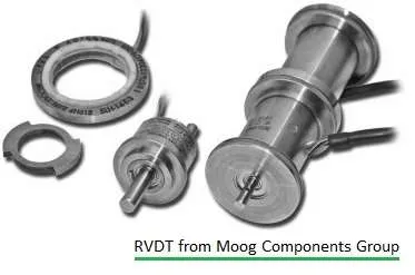
The RVDT sensor functions on the same principle as the LVDT sensor, but it uses a rotary ferromagnetic core to measure angular displacement. Its primary application is in measuring angular displacement.
The linear range of measurement is approximately +/-40 degrees, with a nonlinearity error of around 1%.
The RVDT is essentially an electromechanical transducer that generates a variable AC output voltage linearly proportional to the angular displacement of the input shaft. When a fixed AC source is used, the output is linear within a certain range over the angular displacement.
LVDT vs. RVDT: Key Differences
| Feature | LVDT | RVDT |
|---|---|---|
| Measurement Range | +/-100µm to +/-25 cm | Linear over a range of around +/-40 degrees. |
| Sensitivity | 2 to 3 mV/Volt/degree of rotation | 2.4 mV/Volt/degree of rotation |
| Input Voltage | 1V to 24V rms (50 Hz to 0 KHz frequency) | About 3V (400Hz to 20 KHz frequency) |