RF
RFPCM vs PDM: Understanding the Key Differences
Advertisement
This page compares PCM vs PDM and highlights the differences between PCM (pulse-code modulation) and PDM (pulse-density modulation).
PCM | Pulse Code Modulation
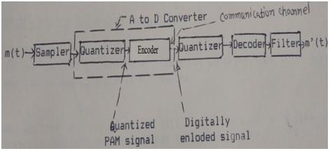
In this modulation technique, an ADC (Analog to Digital converter) is used to convert an analog waveform into a multi-bit digital code. The analog waveform is first sampled and quantized before the samples are represented in binary form.
PCM modulation converts a CA-CT (Continuous Amplitude Continuous Time) waveform into a DA-DT (Discrete Amplitude Discrete Time) waveform.
The sampling rate should be greater than or equal to the Nyquist rate in order to avoid aliasing.
If there is an n bit quantizer and the sampling rate is Fs, then the bit rate will be:
Rb(bits/sec) = n * Fs
The Signal to Quantization Noise Ratio (SQNR) for PCM with a sinusoidal input is:
SQNR (dB) = 6*n + 1.76, where n is the number of bits of the uniform quantizer.
There are two variants of PCM:
- DPCM (Delta Pulse Code Modulation)
- ADPCM (Adaptive Delta Pulse Code Modulation).
PDM | Pulse Density Modulation
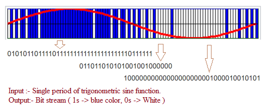
PDM converts a sampled signal to a stream of single bits. It is often referred to as “oversampled 1 bit audio”. In Pulse Density Modulation, specific amplitude levels are mapped using the relative density of pulses.
The following figure depicts a PDM modulated output binary stream. The analog signal is first amplified and sampled at a high sampling rate, and later quantized in the PDM modulator. The reverse processing is carried out in the PDM demodulator.
PDM can be expressed using the following formula:
x[n] = - A (-1) a[n]
Where:
- x[n] is a bipolar stream with either -A or +A
- a[n] is a binary stream with either ‘0’ or ‘1’
Here, ‘1’ corresponds to a pulse with positive polarity and ‘0’ corresponds to a pulse with negative polarity.
Difference between PCM and PDM
The following table highlights the differences between PCM and PDM techniques.
| Parameters | PCM | PDM |
|---|---|---|
| Full Name | Pulse Code Modulation | Pulse Density Modulation |
| How it works | Amplitude levels are mapped to codewords of pulses with different weights. | Amplitude levels are mapped with the relative density of pulses. |
| Performance | Better performance due to multi-point representation. | Poorer performance due to single bit representation. |
| Overload condition | Overload appears when modulating signal changes between samplings, by an amount greater than the size of the step. | PDM modulator is overloaded when the input level exceeds the maximum input level defined. This results in poor noise performance of the modulated signal. |
| Transmission Bandwidth | Larger | Smaller |
| ADC/DAC converter | Multi-bit | Single bit |
| Application | Used as a standard form for digital audio waveforms in desktop PCs, CDs, digital telephony, satellite communication, etc. | Used to deliver audio from microphones to signal processors in smartphones or mobile phones. |
| Complexity | Complex as it uses multi-bits | Simple as it uses only 1 bit to convey audio |
Advertisement