 RF
RFDickson vs. Cockcroft-Walton Voltage Multipliers: A Comparison
Advertisement
This article compares the Dickson voltage multiplier circuit and the Cockcroft-Walton voltage multiplier circuit, highlighting the differences between them and discussing their respective advantages and disadvantages.
Introduction:
When radio frequency (RF) energy travels through free space, it experiences attenuation, resulting in lower power levels at the receiver. Consequently, signal amplification is necessary at the receiver to ensure sufficient power to drive the load or other circuit components. A voltage multiplier or power amplifier is employed for this purpose after the antenna impedance matching circuit.
Voltage multipliers offer the benefit of generating higher output voltages from lower input voltage sources and do not require a transformer. However, a drawback is the output voltage drop with higher resistance values. Both the Dickson and Cockcroft-Walton circuits are used as voltage multipliers, producing output voltages greater than the applied input voltage. These circuits consist of diodes and capacitors arranged in specific configurations.
Cockcroft-Walton Voltage Multiplier
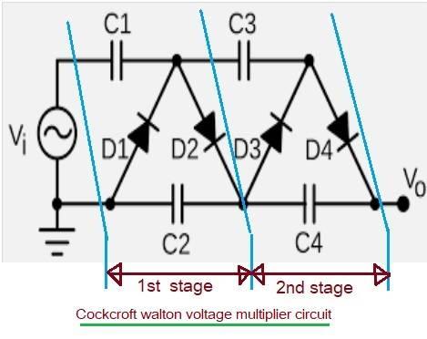
Figure 1: Cockcroft-Walton Voltage Multiplier Circuit
Figure 1 depicts a two-stage Cockcroft-Walton voltage multiplier circuit. It’s often used for low-voltage to high-voltage conversion. In this circuit, all the coupling capacitors are connected in series. This configuration can lead to a significant voltage drop under load, especially when the number of stages is increased. The Dickson circuit aims to overcome this limitation.
Dickson Voltage Multiplier
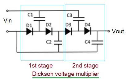
Figure 2: Dickson Voltage Multiplier Circuit
Figure 2 shows a two-stage Dickson voltage multiplier circuit. It’s used for converting low AC voltage to high DC voltage. This circuit arranges all the capacitors in parallel. As a result, it mitigates the voltage drop issue observed in the Cockcroft-Walton circuit. However, it exhibits large capacitor voltage stress at the final multiplier stage.
Hybrid Structures
To leverage the benefits of both circuits, hybrid structures have been implemented, arranging some capacitors in series and others in parallel. Other variants of the Dickson multiplier include the Dickson charge pump using CMOS technology and the differential drive multiplier.
Advertisement


