Balun vs. Antenna Tuner: Impedance Matching Explained
Advertisement
This page compares Baluns and Antenna Tuners, both used as impedance matching devices. Let’s dive in!
There are several impedance matching techniques out there, all designed to connect two lines with different impedances while minimizing signal loss. Popular methods include using stubs or Q-sections with a length equal to λ/4. The impedance of the Q-section (ZQ) can be calculated as:
ZQ = √(ZL * ZO)
Where:
- ZO is the source line or input impedance
- ZL is the load line or output impedance
- ZQ is the characteristic impedance of the stub or Q section
Balun
The term “Balun” is short for “Balanced-Unbalanced transformer.” Essentially, it’s a type of transformer used to match two different impedances.
Most baluns are constructed using a ferrite core (either a toroid or a rod) and copper wire windings. A key advantage of baluns is their broad bandwidth, meaning they perform well across a wide range of frequencies.
Baluns can be designed to produce different impedance matching ratios, such as 4:1, 9:1, or 16:1, depending on the specific application.
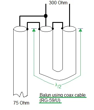
Fig.1 Balun
Baluns can even be made using coaxial cable! A half-wavelength section of coax can be used between the feed line and the antenna. This configuration is often used to convert a 300 Ohm antenna to a 75 Ohm load, or vice versa.
Antenna Tuner
Antenna tuners come into play when a balun isn’t quite enough to do the job.
They are made of inductors and capacitors arranged in various configurations. The most common configurations are L-type, T-type, and Pi-type.
The values of the inductors and capacitors are adjusted to achieve the desired impedance matching based on the SWR (Standing Wave Ratio) requirement. This allows for fine tuning the impedance match between the transmitter and the antenna.