Analog Switch vs. Digital Switch: Key Differences Explained
Advertisement
This article compares analog and digital switches, outlining the differences in their definitions and working principles. Understanding these differences is crucial for selecting the right switch for your application.
Introduction
We know there are two fundamental types of signals: analog and digital. Both are used to transmit information, but they do so in different ways.
- Analog signals are continuous, changing smoothly over time.
- Digital signals are discrete, changing in specific steps to represent digital information as zeros and ones.
Analog signals are often visualized as sine waves, while digital signals are typically represented by square waves.
Analog Switch

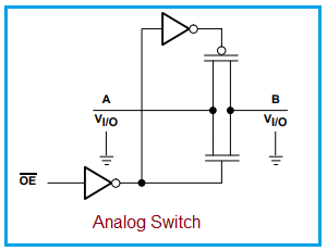
Figure-1 : Analog Switch, Image Courtesy: Texas Instruments
- Function: Analog switches are designed to pass or isolate analog signals. They essentially route analog signals based on a control signal.
- Examples: The CD4066B (CMOS Quad Bilateral Switch) and the SN74HC4066 (quadruple bilateral analog switch) from Texas Instruments are popular examples.
- Analog switches often exhibit decent performance with digital signals as well.
- They function similarly to relays, but without any moving parts.
- They are also known as bilateral switches because they allow signals to pass in both directions.
- Analog switches are available in various packages, including through-hole and surface mount technology.
How Analog Switches Work
Analog switches usually consist of a pair of MOSFET transistors: one N-channel device and one P-channel device. The device can pass signals in either direction when ON and isolates the terminals when OFF. Control inputs with positive and negative voltages are used to turn the device ON and OFF, respectively. This configuration is known as a parallel n-channel/p-channel FET switch.

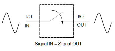
Figure-2: Ideal switch working, Image Courtesy: Texas Instruments
Ideally, an input signal applied at the “left I/O pin” of a switch would produce an identical output signal at the “right I/O pin”. However, in practice, some signal loss occurs during the transfer from input to output.
Analog switches are mainly of two types: mechanical and solid-state. Solid-state switches are typically built using CMOS or FET devices.
Key Specifications of Analog Switches
When selecting an analog switch, consider the following specifications:
- On-resistance: The resistance between the input and output terminals when the switch is ON (typically in the range of a few hundred ohms).
- Off-resistance: The resistance between the input and output terminals when the switch is OFF (typically in the megaohms or gigaohms range).
- Signal Range: The range of voltages (from minimum to maximum) that can be passed through the switch.
- Charge Injection: The injection of a small electric charge into the signal when the switch is turned ON, causing a small spike or glitch.
- Feedthrough: The switch’s ability to block signals when it is OFF. Parasitic capacitance can allow higher frequencies to pass through, making the switch appear to be in the ON state.
- Crosstalk: Two types exist: control (enable) to output crosstalk and crosstalk between switches. The first refers to how well the control signal input is decoupled from the switch’s output.
Digital Switch

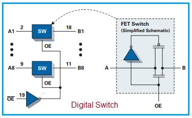
Figure-3 : Digital Switch, Image Courtesy: Texas Instruments
- Function: Digital switches are designed to pass or isolate digital signals.
- Examples: CBT and CBTLV digital switches from Texas Instruments.
- Digital switches can also adequately pass analog signals.
- Digital switches are used in computing applications for multi-bit switching.
- They have a wide range of applications, including multiplexing of USB peripherals and Ethernet multiplexing.
The figure above depicts a digital switch logic diagram. Multiple digital switches are incorporated between input lines (A1 to A8) and output lines (B1 to B8). An OE’ signal is used to enable the switch in different states (ON or OFF).
Analog Switch vs. Digital Switch: A Comparison
The following table highlights the key differences between analog and digital switches.
| Feature | Analog Switch | Digital Switch |
|---|---|---|
| Signal Type | Operates mainly on analog signals | Operates mainly on digital signals |
| Power Consumption | High power consumption | Low power consumption |
| Performance | Lower performance | Higher performance |
| Speed | Lower speed due to analog components | Higher speed of operation |
| Storage | Cannot be stored. | Can be stored digitally with minimal space |
| Cost | More expensive | Less expensive |
Conclusion
Understanding these differences is crucial for selecting the appropriate switch type to ensure optimal performance in electronic circuit designs.
Advertisement
 RF
RF


