2FSK vs 4FSK: Understanding the Differences
Advertisement
This article compares 2FSK (2-level Frequency Shift Keying) and 4FSK (4-level Frequency Shift Keying) modulation techniques, highlighting the key differences between them. We’ll also touch on where these modulation schemes are used in modern digital radio systems.
FSK, in general, is a modulation technique where the carrier frequency is varied according to the baseband digital input signal, while the amplitude remains constant. This makes it relatively immune to noise, a desirable characteristic in digital radio. Essentially, different frequencies represent different digital binary data. A FSK demodulator extracts the data by distinguishing the different frequency deviations with respect to the reference carrier frequency used in the FSK modulator.
2FSK Modulation
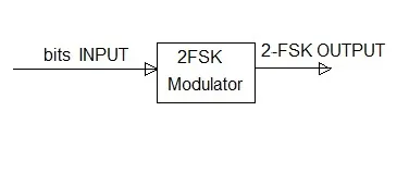
Figure-1 shows a typical 2FSK modulator block. Binary digits (0 or 1) are fed as inputs, and corresponding symbols are generated as outputs. Each symbol in 2FSK carries 1 bit of information. In essence, 2FSK is FSK.
Table 1 shows the typical mapping between input bits and output frequencies:
| Symbol | Input | Coding |
|---|---|---|
| 0 | carrier - deviation (some offset) | |
| 1 | carrier + deviation |
Mathematically, 2FSK modulation can be expressed as:
S1(t) = AcCos[2π(Fc+Δf)t] S2(t) = AcCos[2*π(Fc-Δf)*t]
Where:
- S1(t) represents the output when the input is binary ‘1’
- S2(t) represents the output when the input is binary ‘0’
- Ac is the carrier amplitude
- Fc is the carrier frequency
- Δf is the frequency deviation
4FSK Modulation
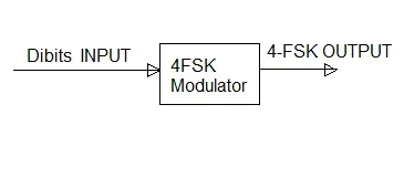
Figure-2 illustrates a 4FSK modulator block. In this case, dibits (pairs of bits: 00, 01, 10, or 11) are used as inputs to generate output symbols. Each symbol carries 2 bits of information. This means that the data rate of 4FSK is double that of 2FSK for the same symbol rate.
Table 2 outlines a possible mapping between input dibits and corresponding output frequencies:
| Symbol | input | Coding (carrier+Δf value used to map input dibits) |
|---|---|---|
| 01 | carrier - deviation | |
| 00 | carrier - (1/3)*deviation | |
| 10 | carrier + (1/3)*deviation | |
| 11 | carrier + deviation |
Similar to 2FSK, 4FSK modulation can be expressed using the following equation:
S(t) = AcCos[2π(Fc+Δf)*t]
In 4FSK, four different Δf values (as shown in Table 2) are used to represent the four different binary dibits, resulting in corresponding output frequencies.
Power Spectrum Comparison
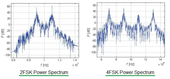
Figure 3 compares the power spectrums of 2FSK and 4FSK.
As the figure demonstrates, 2FSK modulation exhibits two distinct carrier peaks, while 4FSK modulation displays four carrier peaks. This difference arises from the fact that 2FSK represents data using two carrier phase shifts relative to the main carrier frequency, whereas 4FSK uses four carrier phase shifts.
Applications of 4FSK
Digital radio technologies such as DMR (Digital Mobile Radio), dPMR (Digital Private Mobile Radio), LMR and NXDN commonly utilize 4FSK modulation.