 RF
RFTypes of coaxial lines or cables in microwave
Advertisement
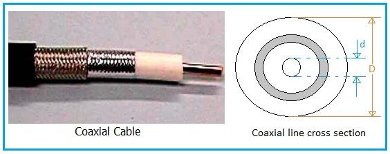
A coaxial line is a type of transmission line used to transport RF (Radio Frequency) energy from one port or part of a system to another. The standard coaxial cable you might be familiar with is often used as a microwave coaxial line.
This type of line usually has two conductors, cylindrical in shape and arranged around a common axis. They are separated by a dielectric material. At lower frequencies, polyethylene is commonly used as the dielectric, while at higher frequencies, Teflon is preferred.
Types of Coaxial Lines
There are various types of coaxial lines, differentiated by their conductor structure and shielding methods. These include:
-
Flexible coaxial cable is often used in TV broadcast receiving antennas, and its outer conductor is made of foil or braid. At microwave frequencies, the outer conductor is typically rigid, and the dielectric is solid.
-
In a gas filled coaxial cable, the center conductor is often supported by thin ceramic insulators, and Teflon can also be used. Dry nitrogen can be used as the dielectric material in these cables.
-
In an articulated coaxial line, the inner insulator is ridged around the inner conductor. Around that is the shield conductor, and around that, a protective insulating sheath.
-
A double shielded coaxial line has two layers of protection, with inner and outer shield layers. This protects the signal from EMI (Electromagnetic Interference) and prevents radiation from the cable from affecting nearby systems.
Characteristic Impedance of Coaxial Line
The characteristic impedance of a basic coaxial cable can be determined using the following equation:
Where:
- Zo is characteristic impedance in Ohm
- K is the dielectric constant of the insulator between the inner and outer conductors.
- D is the diameter of the outer conductor.
- d is the diameter of the inner conductor.
Advantages and Disadvantages of Coaxial Cables
Following are benefits of coaxial cables.
- Supports wide frequency ranges.
- Houses strong shielding which resists EM interference.
- Mechanically robust
- Relatively inexpensive
- Carry signal to longer distances compared to twisted pair cables.
Following are drawbacks of coaxial cables.
- They are thicker and stiffer.
- Often requires amplifiers or repeaters as signal passing through it degrades due to attenuation.
- Easier to tap and hence it is less secure.
Conclusion: Coaxial cables come in a variety of types; each optimized for specific use cases like CCTV, satellite TV or RF systems. They have become popular due to its better shielding, lower attenuation nd are ideal for high frequency signals and longer distances .
Advertisement


