 RF
RFMillimeter Wave Up Converter and Down Converter Design
Advertisement
Millimeter-wave (mmWave) up-converter and down-converter designs are crucial components in modern wireless communication systems, particularly in 5G, satellite communications, and radar systems. These converters are responsible for shifting signals between different frequency bands, enabling efficient transmission and reception over the mmWave spectrum, typically between 24 GHz and 100 GHz. The design of up and down converters requires careful consideration of factors such as signal linearity, noise figure, bandwidth, and frequency stability to ensure optimal performance in high-frequency applications.
This article describes the design of a Millimeter wave up converter and a Millimeter wave down converter with examples. Both millimeter wave up converters and down converters are parts of a millimeter wave transceiver.
Basic Design Approach for Up Converter and Down Converter
Both transmitter and receiver use one or more RF mixers for frequency conversion. As the transmitter does up conversion of frequency, it is also known as the up converter, whereas as the receiver does down conversion of frequency, it is known as the down converter. This is shown in the figure-1 below.
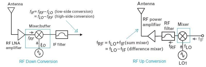
For Fin as the input frequency, FLO as the local oscillator input, and Fout as the output frequency of the RF mixer. They are expressed as follows.
Fout = +/-mFin +/-nFLO
where m and n range from 0,1,2,3…
The RF mixer produces the sum as well as the difference of the input frequencies. The appropriate component is filtered out as per requirement in the system as shown.
Millimeter Wave Up Converter Design
Before we dig into millimeter wave up conversion, let us understand the design approach used in a C band up converter.
The figure-2 depicts the basic design of an up converter at C band frequency.
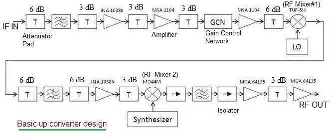
The design is based on heterodyne architecture which uses two RF mixers in the chain rather than homodyne where one RF mixer is used.
- The first mixer converts IF frequency (52 to 88 MHz) to 1182.5 +/- 18 MHz using a Local Oscillator frequency of 1112.5 MHz.
- The second mixer converts this IF frequency to RF frequency in the range 5925 to 6425 MHz using an RF synthesizer of 4680 to 5375 MHz.
- In between, amplifier and attenuator pads (3 dB or 6 dB) are used to meet the Output/Input P1dB compression point requirement of mixers and other amplifier devices in the chain.
- Isolators are used to pass the signal only in the forward direction and block the signal in the reverse direction.
- GCN is the “Gain Control Network.” It is a PIN diode-based attenuator used to vary the output power of the up converter. There are digital attenuators available used for the same purpose.
- RF filters are used at various stages in the up converter chain to filter out desired frequencies and reject the undesired ones. For example, at the input LPF is used to pass low frequencies in the range from 52 to 88 MHz. In the center stage after the first mixer, a BPF of 1182.5+/-18 MHz is used. After the second mixer, BPF of 5925 to 6425 MHz range is used and so on.
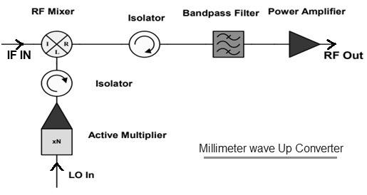
The figure-3 depicts the design of a millimeter wave up converter. It uses a single mixer for RF up conversion. The LO frequency is multiplied and passed to the RF mixer as input in order to beat with the IF Input. The RF mixer output is passed through the isolator and BPF before being amplified by PA (Power Amplifier). One more isolator is used after the multiplier as shown to avoid any reflection of the LO signal back.
Example:
- IF input frequency: 11 to 16 GHz
- Synthesized LO : 16.3 GHz to 18.3 GHz which is multiplied say by 3 times.
- RF output frequency: 57 to 64 GHz
Millimeter Wave Down Converter Design
Let us understand C band down conversion before we dig into the design of the millimeter wave down converter.
The figure-4 depicts the basic line diagram of a down converter used for C band frequency. The design is based on heterodyne architecture as described above in the up conversion chain.
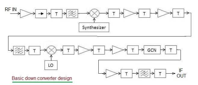
Here initially the first RF mixer converts RF frequency (3700 to 4200 MHz) to IF frequency (1042.5 +/- 18 MHz). The second RF mixer converts IF frequency to baseband IF frequency output (52 to 88 MHz).
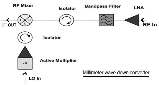
The figure-5 depicts the millimeter wave down converter using a single RF mixer approach. It uses a single RF mixer for down conversion.
Conclusion
The design of millimeter-wave up-converters and down-converters is key to unlocking the full potential of mmWave technology in high-speed wireless communication and radar systems. As mmWave technologies advance, the development of high-performance, low-noise converters will continue to be a focal point for improving signal integrity and efficiency in next-generation communication systems. Reliable converter designs will be instrumental in meeting the growing demand for faster data rates, higher bandwidth, and enhanced connectivity in future wireless networks.
Advertisement


