PIN Diode Modulator for Amplitude Modulation
Advertisement
A PIN diode is a specialized type of diode that incorporates an intrinsic (I) layer between the P-type and N-type regions. This structure—P-type, Intrinsic, and N-type—gives it unique characteristics. The intrinsic layer, a lightly doped semiconductor, acts as a high-resistance barrier.
PIN diodes boast several advantageous features, including:
- Low capacitance
- Fast switching speed
- Variable resistance
These features make them useful in various applications, such as:
- RF switching
- Variable attenuators
- RF phase shifters
- Frequency limiting
- Harmonic generation
- High-voltage rectification
One notable application is the PIN diode AM modulator, where the diode acts as a modulator to impose a modulating signal onto a carrier wave, generating an Amplitude Modulated (AM) waveform. PIN diodes are particularly useful in high-frequency AM modulator circuits operating at UHF, VHF, and microwave frequencies. They are generally designed to operate above 100MHz.
Amplitude modulation, in essence, varies the amplitude of a carrier signal in proportion to the instantaneous amplitude of the information signal (the modulating signal) to transmit data. When a PIN diode is forward biased, it behaves like a variable resistor. This characteristic is leveraged in AM circuits by varying the forward bias of the PIN diode in accordance with the modulating signal.
The resistance of the diode is inversely proportional to the current flowing through it: high current leads to low resistance, and low current leads to high resistance.
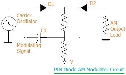
Figure-1: PIN diode modulator circuit
This variable resistance property is key to the AM modulator circuit. Here, the modulating signal controls the forward bias current through the PIN diode, resulting in the generation of an amplitude-modulated (AM) signal. The fast response time of the PIN diode allows for high-speed amplitude modulation.
As depicted in the pin diode circuit diagram in Figure 1, a positive-going modulating signal reduces the bias on the PIN diodes, causing their resistance to increase. This leads to a reduction in the amplitude of the carrier signal across the load. Conversely, a negative-going modulating signal adds to the forward bias, decreasing the diode’s resistance and increasing the carrier amplitude across the load.
A variation of this circuit utilizes a PI network arrangement of diodes as an AM modulator. This design uses three diodes instead of two.
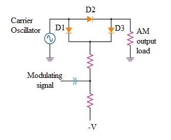
Figure-2: PIN diode modulator
The PIN diode circuit acts as a variable attenuator, reducing the amplitude of the signal. To compensate for power loss, amplifiers are often used to boost the AM signal to a sufficient power level.
Conclusion:
PIN diodes are integral to amplitude modulation (AM) and other modulation techniques. By varying the bias across the intrinsic layer, PIN diodes can effectively modulate the amplitude of a carrier signal. The combination of low capacitance, high speed, and variable resistance makes them indispensable in various RF, microwave, and communication systems where precise signal control is paramount.