 RF
RFFiber Optic Testing: A Comprehensive Guide
Advertisement
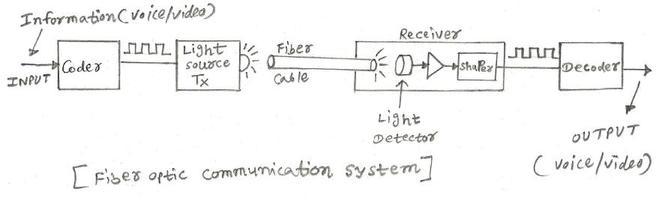
This page explores the various types of testing associated with fiber optic communication links. A typical fiber optic communication system consists of three primary components: a transmitter, a fiber optic cable (the transmission medium), and a receiver.
The transmitter usually incorporates a Light Emitting Diode (LED) which converts digital binary data into light waves. On the receiving end, a photodiode or detector converts these light waves back into digital binary data. Coders and decoders are interfaced when needed.
Fiber optic communication offers several advantages over other transmission methods, such as copper cables and traditional data communication techniques:
- Long-Distance Transmission: Signals can be transmitted over extended distances (approximately 200 km) without requiring signal regeneration.
- Immunity to Interference: Transmission is unaffected by electromagnetic perturbations or RF interference.
- High Capacity: Fiber optic cables boast higher capacity compared to copper or coaxial cables.
- Lightweight and Compact: Fiber optic cables are lighter and smaller than their copper counterparts.
- Vibration Resistance: Optical fibers are not sensitive to vibrations.
- Reliability: Optical fiber offers reliable performance.
Several factors can influence light transmission within a fiber optic communication system. These include attenuation, bandwidth, and dispersion.
Attenuation: As light travels from the transmitting end to the receiving end, it loses optical power due to absorption, scattering, and radiation losses. The presence of noise can sometimes make it challenging to recognize and decode the optical signal.
Bandwidth: Light signals are composed of various frequencies. A fiber optic cable has both upper and lower frequency limits, which constrain the amount of information it can carry.
Dispersion: As a light signal traverses the fiber, pulses of light waves spread out, limiting the information-carrying capacity at high bit rates or over long distances.
Fiber Optic Cable Analysis: Key Measurements
When analyzing a fiber optic cable, several key measurements are performed. These generally fall into the following categories:
- Mechanical Tests
- Geometrical Tests
- Optical Tests
- Transmission Tests
The first three categories (Mechanical, Geometrical and Optical) are typically measured only once, as variations in these properties are minimal over the cable’s lifespan.
Types of Fiber Optic Tests
The table below summarizes the different test categories and specific tests performed under each:
| Mechanical Tests | Geometrical Tests | Optical Tests | Transmission Tests |
|---|---|---|---|
| Traction | Concentricity | Bandwidth | Chromatic Dispersion |
| Torsion | Cylindricity | Optical Power | Polarization Mode Dispersion |
| Bending | Core Diameter | Optical Loss | Attenuation Profile |
| Temperature | Cladding Diameter | Optical Return Loss | |
| Index Profile | Reflectometry | ||
| Numerical Aperture | |||
| Spot Size |
Reference: ITU-T G650 EN 188 000
Advertisement


