 RF
RFAntenna Testing: Radiation Pattern and Gain Measurement Setup
Advertisement
Antenna testing and measurements are essential steps in the development, optimization, and verification of antenna performance. These processes involve assessing various parameters such as radiation pattern, gain, impedance, polarization, and efficiency. A common method for conducting these tests is using a Compact Antenna Test Range (CATR).
Let’s delve into antenna testing and measurements, exploring the antenna radiation pattern measurement setup and antenna gain measurement using a compact antenna test range. As we know, an antenna radiates EM waves in various directions to certain proportions. This radiation is referred to as the radiation pattern of the antenna.
There are two regions around the antenna: the near-field region (< 3λ) and the far-field region (> 3λ).
Antennas can be tested, and various parameters measured, in an indoor chamber or an outdoor range facility.
Antenna Measurements
The following are common antenna measurements tested during antenna testing:
- Antenna Gain: It’s the factor by which the input power to the antenna will be multiplied to provide a higher output power.
- Antenna Beamwidth: The difference between half-power points (3dB points) on the antenna radiation pattern is referred to as the antenna beamwidth. It is measured in degrees.
- Antenna G/T: The Antenna Gain to Noise temperature ratio is referred to as the figure of merit of the antenna.
- Antenna Radiation Pattern: Electromagnetic waves emitted from the antenna are referred to as the antenna radiation pattern. It’s made of a major lobe and more than one side lobe. The region near the antenna is referred to as the near-field region, and the region far away is referred to as the far-field region. It can be represented either in polar or rectangular coordinates.
- Antenna Bandwidth: The range of frequencies over which the antenna operates satisfactorily. The difference between the highest and lowest frequency points is referred to as the antenna bandwidth.
- Antenna Efficiency: It is the ratio of power radiated or power dissipated in the antenna structure to the power input to the antenna.
- Antenna Impedance: In simple terms, it’s the ratio of voltage to the current at the antenna input. If the antenna impedance at the input is 50 Ohms, a sinusoidal voltage amplitude of 1 volt would result in a current amplitude of 1/50 Amps.
- Antenna Effective Aperture: This parameter describes how much power can be captured by the antenna.
Antenna Radiation Pattern Measurement Setup using a Compact Antenna Test Range (CATR)
A CATR setup typically consists of three main components:
-
Antenna Under Test (AUT): This is the antenna that is being tested. It could be any type of antenna, ranging from small printed circuit board antennas to large parabolic dish antennas.
-
Compact Range Reflector: The compact range reflector serves as the main component of the CATR setup. It is a large metallic reflector with a complex shape designed to create a high-quality test zone in its focal region. This test zone should ideally have a plane wavefront, allowing accurate measurement of the AUT’s radiation pattern.
-
Feed System: The feed system is responsible for generating the desired radiation pattern in the test zone. It typically consists of a feed horn or an array of horns that emit a high-quality plane wave toward the reflector. This feed system is carefully designed and calibrated to ensure the accuracy of the measurements.
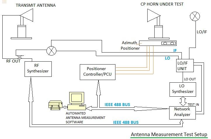
Figure 1: Antenna measurement test setup
The typical setup for antenna testing, used for various antenna measurements, is shown in Figure 1 above. The horn antenna is used as a standard transmitting antenna. The antenna under test (AUT) is used as a receiving antenna in the setup. The AUT is placed on a rotating table or positioner. As mentioned, an RF synthesizer or sweeper is used at the transmitter, which feeds the signal of the desired frequency and power.
The AUT is rotated in azimuth and elevation, and the radiation pattern is recorded at the receiver. For outdoor ranges, the receiving antenna is placed in the far-field region. For indoor ranges, the entire antenna test setup is placed in an anechoic chamber, where the walls are covered with wave-absorbing material. This allows AUT testing free from any building structure and simulates testing as if the antenna is placed in an unbounded free-space medium.
The setup for measuring antenna radiation patterns using a CATR involves the following steps:
- Calibration: Before testing the AUT, the CATR system needs to be calibrated to ensure accurate measurements.
- Positioning the AUT: The AUT is positioned in the test zone of the CATR setup.
- Once the AUT is positioned correctly, measurements of its radiation pattern are conducted by rotating the AUT in azimuth and elevation.
- Data Processing and Analysis: The data collected during the measurement phase are processed and analyzed to generate the radiation pattern of the AUT.
- Finally, the radiation pattern of the AUT is evaluated against the desired specifications or compared with theoretical models.
Various antenna measurements are carried out using this test setup. Typical parameters which are measured include antenna radiation pattern, gain, side-lobes, directivity, HPBW (Half Power Bandwidth), cross-polarization, and back radiation.
Antenna Gain Measurement
Antenna gain is a fundamental parameter that characterizes the ability of an antenna to direct or concentrate its radiated power in a particular direction. It’s a crucial metric for determining how effectively an antenna can transmit or receive signals in a specific direction compared to an ideal isotropic radiator (an antenna that radiates equally in all directions). Antenna gain is typically measured using methods such as the one described above in a Compact Antenna Test Range (CATR).
By following the steps mentioned below, antenna gain can be accurately measured using a CATR setup.
- Before conducting gain measurements, the CATR setup undergoes calibration to ensure accurate results.
- The antenna whose gain is being measured (the AUT) is positioned in the test zone of the CATR setup.
- A reference antenna with known gain characteristics, typically an isotropic antenna or a calibrated standard antenna, is also positioned in the CATR setup.
- The CATR system emits a known signal, typically a plane wave, towards both the AUT and the reference antenna. The signal is then received by each antenna, and the received signal strength is measured.
- The gain of the AUT is calculated by comparing its received signal strength to that of the reference antenna.
Where:
= Power received by the Antenna Under Test (AUT)
= Power received by the reference antenna
- The measured gain values may undergo further processing and analysis to account for any environmental factors, such as reflections or multipath effects, that could affect the measurements.
- Finally, the measured gain values are evaluated against the desired specifications or compared with theoretical predictions.
Conclusion
Overall, the compact antenna test range provides a controlled environment for accurately measuring antenna performance, particularly radiation pattern, which is crucial for various applications such as telecommunications, radar systems, and satellite communications.
Advertisement


