 RF
RFUWB Measurements and UWB Device Conformance Testing
Advertisement
This page covers UWB measurements for transmitter and receiver parts. It describes conformance tests for UWB device transmitter and receiver verification.
Introduction
UWB (Ultra-Wideband) technology spreads RF energy over a wide bandwidth, typically 500 MHz. It adheres to IEEE 802.15.4 and IEEE 802.15.4z standards, which define the PHY (Physical) and MAC (Media Access Control) layers. UWB is used for various applications, including ranging.
The standards define two versions of the Physical layer: HRP (High Rate PHY) and LRP (Low Rate PHY). UWB utilizes 16 frequency channels at different RF frequencies.
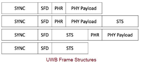
The figure above depicts different frame configurations used in a UWB system. As shown, a frame typically consists of SYNC, SFD, PHR, PHY Payload, and STS fields for desired functions.
The following table outlines the UWB frequencies, UWB channels, and UWB bandwidth used in different regions across the world.
| UWB Channels | UWB Center Frequency | UWB Bandwidth | Region used |
|---|---|---|---|
| 0 | 399.36 MHz | 499.2 MHz | USA |
| 1 | 3494.4 MHz | 499.2 MHz | USA, Europe |
| 2 | 3993.6 MHz | 499.2 MHz | USA, Europe, Japan, Korea |
| 3 | 4492.8 MHz | 499.2 MHz | USA, Europe, Japan, Korea |
| 4 | 3993.6 MHz | 1331.2 MHz | USA, Europe |
| 5 | 6489.6 MHz | 499.2 MHz | USA, Europe, China |
| 6 | 6988.8 MHz | 499.2 MHz | USA, Europe, China |
| 7 | 6489.6 MHz | 1081.6 MHz | USA |
| 8 | 7488 MHz | 499.2 MHz | USA, Europe, Korea, China |
| 9 | 7987.2 MHz | 499.2 MHz | USA, Europe, Japan, Korea, China |
| 10 | 8486.4 MHz | 499.2 MHz | USA, Europe, Japan, Korea, China |
| 11 | 7987.2 MHz | 1331.2 MHz | USA, Japan, Korea |
| 12 | 8985.6 MHz | 499.2 MHz | USA, Japan, Korea |
| 13 | 9484.8 MHz | 499.2 MHz | USA, Japan, Korea |
| 14 | 9984 MHz | 499.2 MHz | USA, Japan, Korea |
| 15 | 9484.8 MHz | 1354.97 MHz | USA, Japan, Korea |
Test and measurement companies such as Rohde & Schwarz, Litepoint, NI (National Instruments), and Keysight Technologies develop test tools for UWB device measurements and its conformance tests. These UWB device test tools allow measurements in the time, frequency, and modulation domains, as per UWB conformance test requirement specifications.
UWB Transmitter Measurements
The following UWB transmitter measurements are conducted during UWB device conformance testing to verify its transmit functionality. These tests focus on verifying the performance of the transmitter. These measurements are typically made using a UWB analyzer tool or a UWB signal analyzer instrument. Various parameters need to be configured to analyze the UWB signal correctly in the UWB test hardware and software.
| UWB Measurements | Description |
|---|---|
| Transmit Power Spectral Density (PSD) test | It tests the maximum transmit power from the UWB device against limits set by national regulatory authorities in various countries for all frequency channels. It should not exceed -41.3 dBm/MHz. |
| Spectral emission mask or PSD mask | It is measured in the frequency domain and defines limits at various frequency offsets from the center carrier frequency. The following mask is as per IEEE 802.15.4z. Here dBr stands for the relative spectral limit compared to the peak transmit power. |
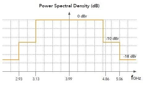 | |
| Transmit power vs time | It measures instantaneous transmit power across a time scale. |
| Center frequency tolerance (CF Offset) | The UWB device should transmit at specified channel frequencies with a frequency offset tolerance of about +/-20 ppm. This is as per the IEEE 802.15.4z compliance specification. |
UWB Receiver Measurements
The following UWB receiver measurements are conducted for its receive functionality verification. These tests focus on verifying reception and checking the sensitivity limit of the UWB DUT (Device Under Test). A UWB signal generator instrument is used to generate UWB compliant signals for receiver tests.
Various parameters need to be set to generate the UWB signal, both in the hardware and in the T&M software. These parameters include channel number, center frequency, power level, waveform settings (e.g., the number of frames), PHY configuration (Data, Preamble, and STS related settings), MAC configuration (Frame control settings, addressing field settings, payload settings), and impairments (AWGN, frequency offset, IQ DC offset, IQ gain imbalance, quadrature skew), etc.
| UWB Measurements | Description |
|---|---|
| Sensitivity test or Packet Error rate (PER) | It is conducted to test if the minimum sensitivity level meets the requirement for different data rates. Less than 1% PER at the specified receiver input level should be achieved for the UWB DUT. |
| Interference test | It measures the interference susceptibility of the UWB receiver with respect to out-of-band unwanted channels that are non-adjacent. |
| Adjacent channel rejection | This test measures the performance of the UWB receiver with respect to nearby undesired channels. It measures adjacent channel selectivity. |
| Maximum receiver input power level | It measures the maximum power that can be given to the receiver without causing any damage. |
Other UWB Pulse Related Measurements
The following are useful measurements provided by many UWB tools from Test and Measurement vendors.
| UWB Measurements | Description |
|---|---|
| Symbol Modulation accuracy | It is the deviation between the ideal symbol and the measured symbol of the received signal. It is measured in EVM (%). Here EVM stands for Error Vector Magnitude. 100% represents a perfect number. |
| Chip clock error | The device should chip at a peak PRF of 499.2 MHz with +/- 20 ppm accuracy (IEEE 802.15.4z). |
| Chip frequency error | The center frequency of pulses are measured. The measured error should be less than +/- 20 ppm tolerance. RBW and VBW should be set to 1 MHz and 1 KHz, respectively, for this test. |
| Average/peak power (Preamble, data, STS) | It measures the average power and peak power of the preamble, data, and STS fields. |
| Packet measurements | Packet auto-detection, data rate, payload length, PHY/MAC payload, number of erroneous packets, STS decoded data, etc. Some UWB test analyzers provide these decoding results. |
| Ranging test | Used for distance measurement using the ToF (Time of Flight) method between the initiator and responder (or receiver). |
Other pulse-related UWB measurements include pulse main lobe width (section 16.4.5 of IEEE 802.15.4z), pulse side lobe power (section 16.4.5), jitter, and the time domain mask.
Advertisement


