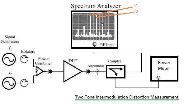
RF Intermodulation Distortion Measurement and Two-Tone Test Setup
Advertisement
RF intermodulation distortion (IMD) measurement is a crucial step in evaluating the performance of RF systems, especially when multiple signals are present. IMD can introduce unwanted interference, degrading signal quality and reducing system efficiency. To simulate real-world operating conditions, test setups typically include two-tone signal generators, spectrum analyzers, and attenuators. This guide covers the necessary measurement techniques, important considerations, and practical steps for accurate IMD analysis, ultimately leading to improved system performance.
When two frequency signals (let’s call them and ) are fed into a nonlinear device, such as an amplifier, the device will amplify the signals at and . However, it will also generate IMD products at other, unwanted frequencies (+/-n*+/-m*).
Frequencies at -, -, 2, and 2 are known as second-order IMD products. Meanwhile, frequencies at 2- and 2-, 3, and 3 are known as third-order IMD products.
The frequencies at 2- and 2- are often the most significant and therefore require measurement. Measuring these intermodulation distortion (IMD) products at 2- and 2- is known as the two-tone test method.
Refer to “Second VS Third Order Intercept Point Basics” for more information.
Two-Tone Test Equipment for IMD Testing
The following equipment is needed for an intermodulation distortion measurement setup:
- RF Spectrum analyzer
- RF Isolators
- RF Power Combiner
- RF Power Meter
- Device Under Test (DUT)
- Two RF signal generators or CW sources
- RF Attenuator (Fixed or variable)
- RF Directional Coupler
Test Procedure for RF Intermodulation Distortion Measurement

The following test procedure is used for intermodulation distortion measurement:
- Set up the equipment as shown in Figure 1 (above).
- Generate continuous wave frequency signals at and using two signal generators. and should be closely spaced frequencies, with a difference of about 1 MHz between them.
- Pass these frequencies through RF isolators individually and combine them using an RF power combiner.
- Feed the combined output as input to the nonlinear DUT.
- The output of the DUT will contain , , and other unwanted intermodulation distortion products, as previously explained. Apply the output to a directional coupler via an RF attenuator.
- Connect the directional coupler output to the RF Input of the Spectrum analyzer. In the spectrum analyzer, set markers at , , and at the frequencies 2- and 2-.
- The difference between the power levels at or and 2- or 2- is known as the intermodulation rejection. It is measured in dBc. A higher rejection value indicates a better system performance.
Conclusion
Accurately measuring RF intermodulation distortion is vital for maintaining system reliability in complex RF environments. Using the right equipment and test methods helps to effectively identify and mitigate interference issues. This knowledge is essential for engineers who aim to optimize RF designs for high performance.
Advertisement
 RF
RF


