RF Harmonic Distortion Measurement Procedure and Test Setup
Advertisement
Introduction
RF harmonic distortion measurement is essential to assess the non-linear behavior of RF components and systems. Harmonics can degrade signal integrity, making their measurement critical in designing efficient RF systems. Test setups typically involve signal generators, spectrum analyzers, and low-pass filters for accurate results. This guide provides a comprehensive overview of measurement procedures and techniques, along with practical tips for setting up reliable tests to ensure system linearity.
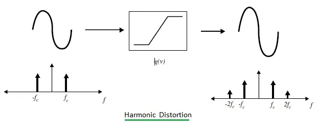
When any input frequency signal is applied to a non-linear device, it will generate unwanted frequencies other than the input signal. These unwanted frequencies, if present at integer multiples of the input frequency, are referred to as harmonics. The figure depicts harmonics (i.e., ), which are at twice the input frequency ().
Test Equipments for Harmonic Distortion Measurement
The following test equipment is needed for the harmonic distortion measurement setup:
- RF Spectrum analyzer used as harmonic distortion analyzer
- RF Power Meter
- Device Under Test (DUT)
- RF signal generator or CW source
- RF Attenuator (Fixed or variable)
- RF Directional Coupler
RF Harmonic Testing Procedure for Harmonic Measurement
The following RF harmonic testing procedure is used for RF harmonic distortion measurement:
-
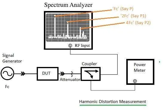
Set up the equipment as shown in Figure 1.
-
Feed the CW frequency (say '') to the non-linear DUT (either RF Transceiver or RF Power Amplifier).
-
Connect the RF attenuator at the output of the DUT and feed the signal output to the directional coupler.
-
Connect one port output of the directional coupler to the RF power meter and the other port to the RF spectrum analyzer, which can be used as a harmonic distortion analyzer.
-
Place the markers at point ‘P’, point ‘P1’, and point ‘P2’.
- P is the reference center frequency ().
- P1 is the first harmonic at .
- P2 is the second harmonic at .
-
The difference between power levels at P and P1 will provide the first harmonic distortion measurement. The difference between power levels at P and P2 will provide the second harmonic distortion measurement.
-
It is measured in dBc. The greater the difference between the points, the better the system.
Conclusion
Understanding and mitigating RF harmonic distortion is crucial for optimizing RF performance. By employing the right test setups and accurate measurement techniques, engineers can identify and address non-linearities effectively. This ensures the delivery of clean signals and enhances overall system efficiency.