RF Gain Flatness: Measurement, Formula & Test Setup Guide
Advertisement
Introduction
RF gain flatness measurement is crucial for evaluating the frequency response consistency of RF components and systems. This process ensures that the gain remains uniform across a specified frequency range, enabling optimal performance in applications like communications and radar systems. Proper test setups, including signal generators, spectrum analyzers, and calibration kits, are key to achieving accurate results. This guide provides insights into measurement techniques, tools, and step-by-step procedures to help you ensure RF system reliability.
The gain flatness is usually given in the technical specifications of RF systems. For example:
- RF Up converter: Gain response should be +/- 1 dB for all the transponders in the range from 5925 to 6425 MHz. For example, +/-1dB for 6175+/-18 MHz as transponder bandwidth is about 36 MHz. Similarly for C band RF down converter from 3700 to 4200 MHz band.
- RF Power Amplifier: +/- 1 dB for C band Frequency from 5925 to 6425 MHz for all the transponders.
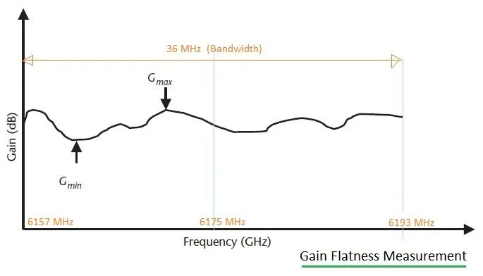
Figure-1 : Gain flatness response
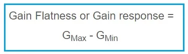
As mentioned, gain flatness is the difference between maximum gain () and minimum gain () measured over frequency range of interest. The flatness measurement formula can be expressed as follows.
Gain Flatness Test Setup
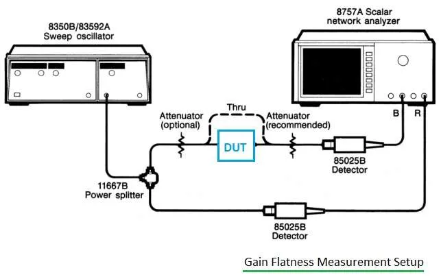
Figure-2 : Gain flatness test setup
Figure 2 depicts a typical gain flatness measurement test setup. As mentioned, tools such as a Sweep Oscillator, Scalar Network Analyzer (SNA), RF detectors, RF power splitter, attenuator pads, and the DUT (Device Under Test) are used.
The following steps are usually performed for gain flatness measurement:
- First, calibrate the SNA for through measurement with all the required RF components needed in the setup, such as the power splitter, detectors, and attenuator pads.
- Set the input frequency range of the DUT as needed in the sweep oscillator before calibration. Also, take care of the desired input power level needed for the Device Under Test, e.g., RF amplifier or RF Up converter module of RF Transceiver.
- Now insert the DUT in the setup. One can observe the gain response as shown in Figure 1 above. Use two markers on the SNA. Keep one on the maximum point and the other on the minimum point. The difference between these two points is known as gain flatness or gain response.
Conclusion
Accurate RF gain flatness measurement is vital for maintaining system performance across the desired frequency range. By using calibrated equipment, following standardized procedures, and regularly verifying your test setups, you can minimize errors and optimize your RF designs. Understanding the nuances of this measurement will help in developing robust, high-performance RF systems such as RF Transceivers, Power Amplifiers, and LNAs.