 RF
RFEcho Canceller Test Procedure and Equipment
Advertisement
This page details the echo canceller test procedure and lists the echo cancellation test equipment used for evaluation.
An echo canceller is a device used for echo cancellation, primarily in telecommunication networks. The measurements performed as part of this test procedure include return loss, line rate, jitter, Echo Return Loss Enhancement (ERLE), continuity, and tone disabler (data transmission, in-band signaling).
About Echo Cancellers
Echo cancellers are primarily used in telecommunication networks to eliminate or reduce echo. They employ advanced Digital Signal Processing (DSP) algorithms to achieve echo cancellation.
The following sections outline various measurements performed on the echo canceller during test evaluation.
Echo Cancellation Test Equipment
The following is a list of test equipment used for echo cancellation testing:
- Sweep Signal Generator
- Spectrum Analyzer
- Directional Coupler
- Termination
- 75 Ohm unbalanced to 120 Ohm balanced Transformer
- PCM Channel Test Set
- Oscilloscope
- Digital Transmission Analyzer (DTA)
- Jitter Modulator Oscilloscope
- 3dB and 6dB pads
- DC regulated power supply
- Digital Volt Meter
Test Procedure for Echo Canceller Measurements
Let’s explore the test procedure for various tests and measurements as part of echo canceller evaluation, both in the lab and in the field.
Output Port Return Loss
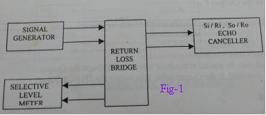
Figure:1
- Connect the test equipment as shown in Figure 1.
- Set the sweep signal generator to the desired frequency.
- Connect the signal generator to the input port of the directional coupler and the output port to the spectrum analyzer.
- Calibrate the spectrum analyzer by shorting the coupled port of the directional coupler.
- Connect the output port of the canceller to the coupled port of the directional coupler and note down the readings.
- The difference between these two readings will give the return loss of the output port.
Perform the above steps for the input port return loss with suitable changes for the input port instead of the output port as the measurement port.
Record the measurements as per the format mentioned in Table 1 below.
Table:1
| Frequency | Specification | Observation |
|---|---|---|
| 51.2 KHz to 102 KHz | >=12 dB | |
| 102 KHz to 2048 KHz | >=18 dB | |
| 2048 KHz to 3072 KHz | >=14 dB |
Pulse Mask Measurement
The line coding used should be HDB3 as per ITU-T Rec. G.703. Output pulse characteristics can be measured by two methods:
- Pulse Mask Method
- CRO Method
In the pulse mask method, a pulse mask is placed at the front-end screen of the CRO. The output pulse characteristics can then be observed. If the output pulse falls within the ITU-T pulse mask, it is considered OK.
The CRO method is described below:
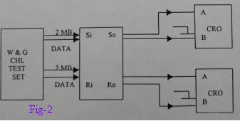
Figure:2
- Make the connections as per Figure 2.
- Feed 2 Mbps data to the Si port of the echo canceller.
- Connect the So port to the CRO through two 60 Ohm resistors as shown.
- Measure the pulse characteristics of both +ve and -ve pulses, and tabulate the results as shown in Table 2.
- Repeat the above echo canceller test procedure for the receive output port also.
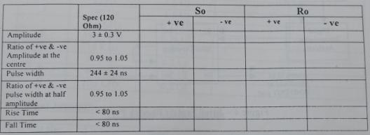
Table:2
Line Rate Measurement
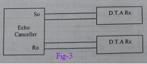
Figure:3
- Connect the Ro port of the echo canceller to the DTA Rx as shown in Figure 3.
- Read the ppm offset on the instrument.
- Then connect the So port of the echo canceller to the DTA Rx and take the measurement as above.
- Record the same in Table 3 below.
Table:3
| SL NO | Specification | R0 | S0 |
|---|---|---|---|
| 1 | 2.048Mbps+/-50ppm |
Input Jitter Tolerance
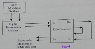
Figure:4
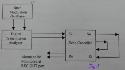
Figure:5
- Feed framed jittery data from the jitter modulation oscillator and digital transmission analyzer to the Ri port of the echo canceller. The pattern of data should be HDB3 coded 215-1 PRBS of frequency and amplitude as defined in Figure 3/G.823 table 2/G.823.
- Short the Ro and Si ports.
- Connect the output port So to the DTA receiver.
- Adjust the jitter frequency to 20 Hz.
- Increase the amplitude until the local LED on the SEND out port glows.
- Reduce the amplitude until the LED turns OFF. Note down the amplitude.
- Repeat the same for various frequencies as per the table.
- Repeat the same test procedures by feeding jittery data at the SEND IN port and monitor at the REC OUT port (Short So and Ri ports).
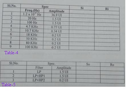
Table:4/5
Echo Return Loss Enhancement (ERLE) Measurement
ERLE (Center Clipper Enabled i.e. NLP ON-ERL 6dB)
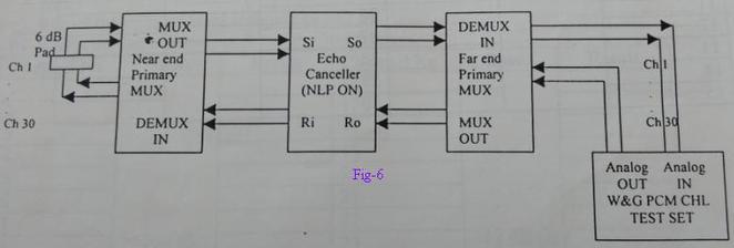
Figure:6
- Connect the equipment as shown in Figure 6.
- Using the front select and advanced switches, select ERL 6 dB.
- Select NLP mode on the front panel. Press the advance switch to go to the ON option.
- Feed a 1 KHz, -10 dBmo audio signal to the 4W Tx points of the far-end primary MUX channel-1.
- Connect a 6 dB pad between the 4W Tx and 4W Rx of the near-end primary MUX channel-1.
- Connect the 4W Rx of channel-1 (far end MUX) to the audio analyzer analog IN port.
- Record the received level. It should be >65 dB.
- Repeat the same test procedure for all 30 channels.
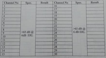
Table:7
ERLE (Center Clipper Enabled i.e. NLP ON-ERL 3dB)
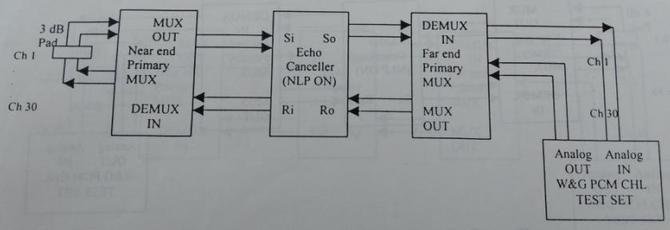
Figure:7
- Connect the equipment as shown in Figure 7.
- Using the front select and advanced switches, select ERL 3 dB.
- Select NLP mode on the front panel. Press the advance switch to go to the ON option.
- Feed a 1 KHz, -10 dBmo audio signal to the 4W Tx points of the far-end primary MUX channel-1.
- Connect a 3 dB pad between the 4W Tx and 4W Rx of the near-end primary MUX channel-1.
- Connect the 4W Rx of channel-1 (far end MUX) to the audio analyzer analog IN port.
- Record the received level. It should be >62 dB.
- Repeat the same test procedure for all 30 channels.
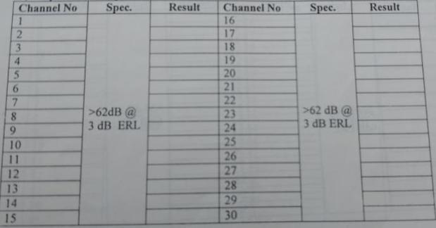
Table:7
ERLE (Center Clipper Disabled i.e. NLP OFF-ERL 6dB)
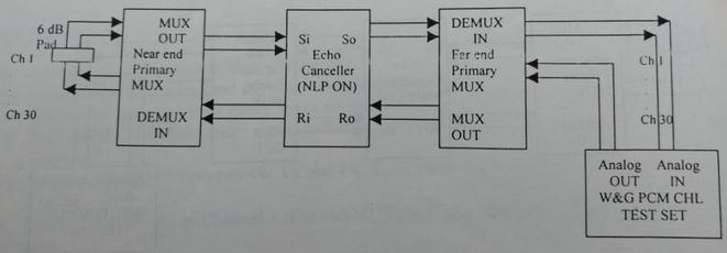
Figure:8
- Connect the equipment as shown in Figure 8.
- Using the front select and advanced switches, select ERL 6 dB.
- Select NLP mode on the front panel. Press the advance switch to go to the OFF option.
- Feed a 1 KHz, -10 dBmo audio signal to the 4W Tx points of the far-end primary MUX channel-1.
- Connect a 6 dB pad between the 4W Tx and 4W Rx of the near-end primary MUX channel-1.
- Connect the 4W Rx of channel-1 (far end MUX) to the audio analyzer analog IN port.
- Record the received level. It should be >35 dB.
- Repeat the same test procedure for all 30 channels.
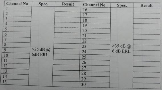
Table:8
ERLE (Center Clipper Disabled i.e. NLP OFF-ERL 3dB)
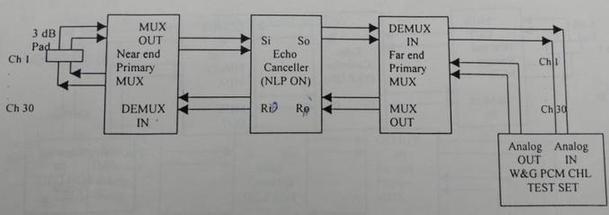
Figure:9
- Connect the equipment as shown in Figure 9.
- Using the front select and advanced switches, select ERL 3 dB.
- Select NLP mode on the front panel. Press the advance switch to go to the OFF option.
- Feed a 1 KHz, -10 dBmo audio signal to the 4W Tx points of the far-end primary MUX channel-1.
- Connect a 3 dB pad between the 4W Tx and 4W Rx of the near-end primary MUX channel-1.
- Connect the 4W Rx of channel-1 (far end MUX) to the audio analyzer analog IN port.
- Record the received level. It should be >32 dB.
- Repeat the same test procedure for all 30 channels.
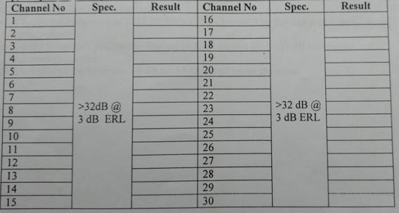
Table:9
Continuity Check Tone: 2000 Hz as per ITU-T CCS-6 and CCS-7
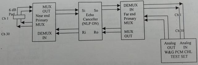
Figure:10
- Make the test setup as shown in Figure 10.
- Select signaling tone disabler mode and press the advance switch to option C6/C7.
- Feed a 2000 Hz analog signal at -10dBmo.
- Record the received analog level in Table 10 below.
Table:10
| Frequency | Input level | Output level |
|---|---|---|
| 2000 Hz | -10 dBmo |
Tone Disabler (for Data Transmission)
- Detection band: mandatory 2079 to 2121 Hz. Optional 1950 to 2079 Hz and 2121 to 2250 Hz.
- Detection threshold: -33 dBmo +/- 2 dB at 2100 Hz.
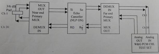
Figure:11
- Make the setup as shown in Figure 11.
- Select data tone disabler mode and press the advance switch to the 2100 option.
- Select 2079 Hz at -10 dBmo from the PCM channel test set and connect the test setup as shown in Figure 11.
- Record the received data tone level.
- Change the frequency to 2121 Hz from the PCM channel test set and repeat the same test procedure.
- Set the frequency in the channel test set to 2100 Hz and feed -31 db and repeat the same test procedure.
- Then change the level to -33dBm, -35dB and repeat the same.
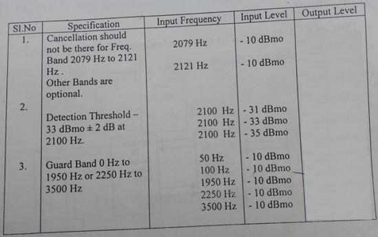
Table:11
Tone Disabler (for In-Band Signaling at 2600 Hz)
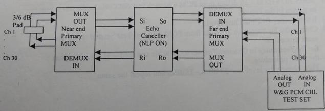
Figure:12
- Detection band: 2600/2400 Hz.
- Detection threshold: Disabling will occur in the detection band for signals greater than -19 dBmo and will not occur for signals less than -22dBmo.
- Connect the test setup as shown in Figure 12 and perform the test procedure similar to the one described above.
Advertisement

