 RF
RFACPR Measurement: Adjacent Channel Power Ratio in RF
Advertisement
The term ACPR refers to Adjacent Channel Power Ratio, a critical parameter in RF (Radio Frequency) and wireless communication systems.
Let’s explore ACPR measurement in RF, including how to measure Adjacent Channel Power Ratio using a test setup block diagram and appropriate test tools/equipment. ACPR is specific to the wireless device under test (DUT) and its compliance with standards like GSM, LTE, WiFi, CDMA, or WiMAX. Accordingly, an IQ file tailored to the respective wireless standard can be used in the measurement setup.
ACPR measures the power of a transmitted signal relative to the power of signals in adjacent frequency channels. High ACPR values can lead to interference with neighboring channels and degrade overall system performance.
Let’s consider an example:
Assume we are performing ACPR measurement of a GSM Device, with the following specification:
ACPR < -65 dBc at 400 kHz with RBW (Resolution Bandwidth) of 30KHz
Test Tools for Adjacent Channel Power Ratio Measurement
The following test tools or equipment are needed for the ACPR RF measurement setup:
- Spectrum analyzer
- Power Meter
- Device Under Test (DUT)
- RF Vector Signal Generator (RF VSG) (Built-in IQ file or external IQ interface)
- RF Attenuator (Fixed or variable)
- RF Directional Coupler
Test Procedure for ACPR Measurement
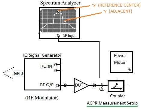
To measure Adjacent Channel Power, you typically need a test setup as per the block diagram below, consisting of the following components.
- Signal Generator: Generates the modulated RF signal you want to measure. It provides the primary signal along with adjacent channel signals.
- RF Spectrum Analyzer: Analyzes the frequency spectrum of the generated signal. It displays the power level of the primary signal and adjacent channel signals.
- Power Meter: Measures the power levels of the signals accurately.
- Filters or Couplers and Attenuators: Condition the signals and ensure only the desired frequency bands are analyzed. Filters help isolate the main channel and adjacent channels, while attenuators adjust the power levels as needed for measurement accuracy. RF couplers are essential in ACPR measurements to isolate the signal path, splitting the signal for simultaneous transmission to the power meter and spectrum analyzer, as shown below. This ensures accurate power monitoring without signal interference.
- Test Cables and Connectors: Ensure signal integrity and minimize losses in the test setup.
The following test procedure is used for ACPR measurement:
-
Set up the equipment as shown in the figure above.
-
Generate a modulated RF signal compliant with the GSM standard using an I/Q baseband vector. This can be done either by playing an IQ file in the RF VSG itself or by externally providing an IQ vector signal using IQ signal generators.
-
The generated IQ signal is converted to an RF vector inside the RF VSG, which is then provided as input to the DUT.
-
Connect the DUT output to the RF directional coupler via an RF attenuator.
-
Connect one output of the RF coupler to the RF power meter and the other output to the RF spectrum analyzer.
-
The RF power meter measures the absolute signal power in dBm.
-
As shown in the figure, set two markers in the RF spectrum analyzer: one at the center frequency (let’s call it ‘X’) and the other at 400 KHz away from the center frequency (let’s call it ‘Y’).
-
The difference between X and Y is taken as the ACPR measurement. This is measured in dBc.
-
You can also use the following ACPR formula to calculate the Adjacent Channel Power Ratio:
Conclusion
In summary, measuring Adjacent Channel Power Ratio (ACPR) is crucial in RF communication systems to assess the interference potential of transmitted signals on adjacent frequency channels. Utilizing proper test setups with RF couplers, spectrum analyzers, and power meters ensures accurate characterization of ACPR, enabling the optimization of system performance and minimizing interference issues in wireless communication networks.
Advertisement


