 RF
RFNI Signal Generator and Analyzer LabVIEW VIs
Advertisement
This page covers the NI RF Signal Generator (RFSG) VI and RF Signal Analyzer (RFSA) LabVIEW VI. These VIs are used to configure NI signal generators and signal analyzers with baseband transmitter and receiver parts for signal transmission and reception, respectively.
Introduction
National Instruments PXI-567x and PXI-566x are capable of RF vector signal generation and RF vector signal analysis. They operate in the frequency range up to 2.7 GHz. Versions of RFSG and RFSA covering RF frequencies up to 6 GHz are also available.
The NI RFSG and RFSA can be used for real-time signal generation according to various wireless standards such as WLAN, WiMAX, Zigbee, etc. Refer to the article on RF signal generation and analysis.
An RF signal generator consists of an AWG (Arbitrary Waveform Generator) and RF up-conversion modules. An RF signal analyzer consists of RF down-conversion and digitizer modules.
NI RF Signal Generator VI | RFSG VI
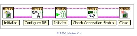
Figure 1 depicts the NI LabVIEW VIs involved in RF signal generation. The following steps are followed to generate an RF vector signal:
- niRFSG Initialize LabVIEW VI: Opens a session to the NI-RFSG device. It initializes the AWG and RF up-converter.
- niRFSG Configure RF LabVIEW VI: Configures the frequency and power level of the RF output vector signal.
- niRFSG Initiate LabVIEW VI: Initiates RF signal generation.
- niRFSG Check Generation Status LabVIEW VI: Monitors RF signal generation status and checks for any errors that may occur during RF signal generation.
- niRFSG Close LabVIEW VI: Closes the NI-RFSG session and de-allocates memory resources used by the NI-RFSG instrument.
NI RF Signal Analyzer VI | RFSA VI
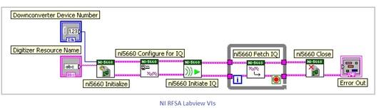
The following steps are followed to analyze an RF vector signal:
- An RF vector signal enters the RF Signal Analyzer module through the INPUT connector.
- The RF downconverter module performs frequency translation to an IF frequency.
- The IF signal output is passed to the IF digitizer module, which filters and provides an analog baseband signal. Proper gain is applied to maintain SNR.
- An ADC converter converts the analog form of the signal to the digital form.
- The digital baseband IQ signal is sent to onboard memory and then transferred to the host computer.
Figure 2 depicts the NI LabVIEW VIs involved in RF signal analysis.
Advertisement


