5G NR Uplink Power Control: Procedure and Equations
Advertisement
This page describes the 5G NR Uplink Power Control Procedure used between the UE and gNB. The uplink power control procedure determines the transmit power of the different uplink physical channels (PUCCH, PUSCH) or signals (SRS, PRACH). The equations and IEs (Information Elements) are also mentioned.
Introduction
In wireless systems, it is often required to either increase or decrease the transmit power of the UE or mobile device. This is known as uplink power control. Transmit power is increased to meet the required SNR or BER at the gNB (or base station or eNB). Transmit power is decreased to minimize co-channel interference in the 5G system.
There are two types of power controls: open loop power control and closed loop power control.
ConfiguredGrantConfigIE defines the “powerControlLoopToUse” field.- The IE
Alphadefines possible values for uplink power control. - In 5G NR, the power control procedure has been modified to work for all the numerologies or subcarrier spacing/other system parameters.
- The term in the following equations supports different 5G NR numerologies. The ranges from 0 to 5 to support various NR numerologies.
- There is a field called “TPC command” which indicates how much power should be reduced or increased. This is mentioned below in the table.
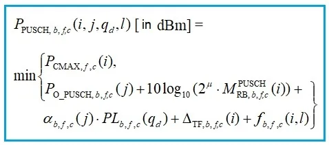
PUSCH | Physical Uplink Shared Channel
The following equation-1 mentions various parameters needed in order to control the power of the PUSCH channel.
The following power control IE (Information Element) is used by RRC for PUSCH.
PUSCH-PowerControl ::=      SEQUENCE {
tpc-Accumulation     ENUMERATED { disabled },
msg3-Alpha      Alpha,
p0-NominalWithoutGrant     INTEGER (-202..24),
p0-AlphaSets      SEQUENCE (SIZE (1..maxNrofP0-PUSCH-AlphaSets)) OF P0-PUSCH-AlphaSet,
pathlossReferenceRSToAddModList     SEQUENCE (SIZE (1..maxNrofPUSCH-PathlossReferenceRSs)) OF PUSCH-PathlossReferenceRS,
pathlossReferenceRSToReleaseList     SEQUENCE (SIZE (1..maxNrofPUSCH-PathlossReferenceRSs)) OF PUSCH-PathlossReferenceRS-Id,
twoPUSCH-PC-AdjustmentStates      ENUMERATED {twoStates},
deltaMCS      ENUMERATED {enabled},
sri-PUSCH-MappingToAddModList      SEQUENCE (SIZE (1..maxNrofSRI-PUSCH-Mappings)) OF SRI-PUSCH-PowerControl,
sri-PUSCH-MappingToReleaseList      SEQUENCE (SIZE (1..maxNrofSRI-PUSCH-Mappings)) OF SRI-PUSCH-PowerControlId
}

P0-PUSCH-AlphaSet ::=      SEQUENCE {
p0-PUSCH-AlphaSetId      P0-PUSCH-AlphaSetId,
p0      INTEGER (-16..15),
alpha      Alpha
}

P0-PUSCH-AlphaSetId ::=      INTEGER (0..maxNrofP0-PUSCH-AlphaSets-1)

PUSCH-PathlossReferenceRS ::=     SEQUENCE {
pusch-PathlossReferenceRS-Id      PUSCH-PathlossReferenceRS-Id,
referenceSignal      CHOICE {
ssb-Index      SSB-Index,
csi-RS-Index      NZP-CSI-RS-ResourceId
}
}

PUSCH-PathlossReferenceRS-Id ::=      INTEGER (0..maxNrofPUSCH-PathlossReferenceRSs-1)

SRI-PUSCH-PowerControl ::=      SEQUENCE {
sri-PUSCH-PowerControlId      SRI-PUSCH-PowerControlId,
sri-PUSCH-PathlossReferenceRS-Id      PUSCH-PathlossReferenceRS-Id,
sri-P0-PUSCH-AlphaSetId      P0-PUSCH-AlphaSetId,
sri-PUSCH-ClosedLoopIndex      ENUMERATED { i0, i1 }
}

SRI-PUSCH-PowerControlId ::=      INTEGER (0..maxNrofSRI-PUSCH-Mappings-1)

BetaOffsets ::=      SEQUENCE {
betaOffsetACK-Index1      INTEGER(0..31),
betaOffsetACK-Index2      INTEGER(0..31),
betaOffsetACK-Index3      INTEGER(0..31),
betaOffsetCSI-Part1-Index1      INTEGER(0..31),
betaOffsetCSI-Part1-Index2      INTEGER(0..31),
betaOffsetCSI-Part2-Index1      INTEGER(0..31),
betaOffsetCSI-Part2-Index2      INTEGER(0..31)
}
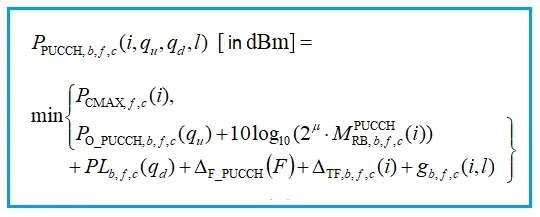
PUCCH | Physical Uplink Control Channel
The following equation-2 mentions various parameters needed in order to control the power of PUCCH channel.
The following power control IE (Information Element) is used by RRC for PUCCH.
PUCCH-PowerControl ::=    SEQUENCE {
deltaF-PUCCH-f0    INTEGER (-16..15),
deltaF-PUCCH-f1    INTEGER (-16..15),
deltaF-PUCCH-f2    INTEGER (-16..15),
deltaF-PUCCH-f3    INTEGER (-16..15),
deltaF-PUCCH-f4    INTEGER (-16..15),
p0-Set   SEQUENCE (SIZE (1..maxNrofPUCCH-P0-PerSet)) OF P0-PUCCH,
pathlossReferenceRSs   SEQUENCE (SIZE (1..maxNrofPUCCH-PathlossReferenceRSs)) OF PUCCH-PathlossReferenceRS,
twoPUCCH-PC-AdjustmentStates   ENUMERATED {twoStates},
...
}

P0-PUCCH ::=   SEQUENCE {
p0-PUCCH-Id   P0-PUCCH-Id,
p0-PUCCH-Value   INTEGER (-16..15)
}

P0-PUCCH-Id ::=    INTEGER (1..8)

PUCCH-PathlossReferenceRS ::=   SEQUENCE {
pucch-PathlossReferenceRS-Id   PUCCH-PathlossReferenceRS-Id,
referenceSignal   CHOICE {
ssb-Index   SSB-Index,
csi-RS-Index   NZP-CSI-RS-ResourceId
}
}
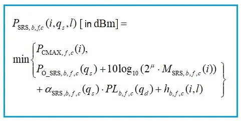
SRS | Sounding Reference Signal
The following equation-3 mentions various parameters needed in order to control the power of SRS signal.
SRS-config IE uses “srs-PowerControlAdjustmentStates” field.
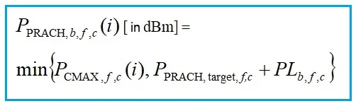
PRACH | Physical Random Access Channel
The following equation-4 mentions various parameters needed in order to control the power of PRACH channel.
PREAMBLE_POWER_RAMPING_STEP field is used during “Random Access Preamble transmission”.
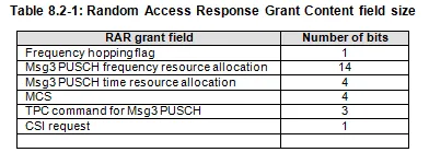
Following are the contents of the random access response grant field.
The following table mentions the meaning of the TPC command field in dB value.
| TPC command value (in dB) | |
|---|---|
| 0 | -6 |
| 1 | -4 |
| 2 | -2 |
| 3 | 0 |
| 4 | 2 |
| 5 | 4 |
| 6 | 6 |
| 7 | 8 |
The total UE transmit power is defined as the sum of the linear values of UE transmit powers for PUSCH, PUCCH, PRACH, and SRS.
References
- Section 7: uplink power control in 3GPP TS 38.213 V15.2.0 (2018-06), (Release 15)
- 3GPP TS 38.331 V15.2.0 (2018-06), (Release 15), RRC protocol specification